Single-Valved Manifolds
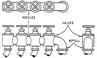
Single-valved manifolds (fig. 4-21) control flow of
JP-5 to and from storage tanks designated either JP-5
or JP-5 overflow. These ranks are not ballasted.
Single-valved manifolds are also used in the service
pump recirculating lines to recirculate fuel back to
the service tank, and as tanktop valves in the
stripping system.
The single-valved manifold is nearly identical to
the tankside half of the double-valved manifold with
one major exception. Instead of the nozzle connecting
it to a transfer mainside valve, the nozzles in a single
valve manifold connect to each other. There is NO
transfer mainside valve. A minor difference is single-
valved manifolds come in different sizes, based on
intended use. A 90-degree ell flanged on one end is
used to bolt the single-valved manifold to its
respective branch header.
Figure 4-21.—Single-valved manifold.
Flood and Drain Manifolds
Flood and drain manifolds are located in the
strip-ping system between the single-valved stripping
manifolds and the stripping pumps FOR TANKS
DESIGNATED AS JP-5 OR BALLAST only. They are
designed to direct the flow of liquids to and from the
JP-5 storage tanks during the following operations
from one central location:
When designated tanks are ballasted, they direct the
flow of sea water from the sea chest supply riser to
the single-valves stripping manifold.
When designated tanks are deballasted, they direct
the flow of ballast water from the single-valved
stripping manifold to the main drainage eductor.
When the designated tanks are stripped, they direct
the stripped liquids from the single-valved strip-ping
manifold to the suction side of the stripping pumps.
A flood and drain manifold (fig. 4-22) consists of
a manifold header and three globe type shutoff
valves.
The manifold header is a common valve body for all
three valves. It contains three valve seats and forms
an unrestricted passage between the three valves
above the valve seats. One end of the header is bolted
to the single-valved stripping manifold. The other end
is sealed. The upper part of the header houses the
valve bonnet, which provides a working area for the
valve stem. A gasket is installed between the bonnet
and the header. A packing gland in the valve bonnet
prevents liquids from leaking around the stem. The
lower part of the header, below the valve seats, has
Figure 4-22.—Flood and drain manifold.
4-25


