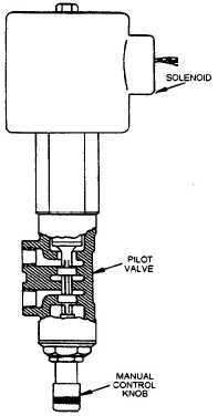
Figure 5-7.-Solenoid-operated pilot valve (SOPV).
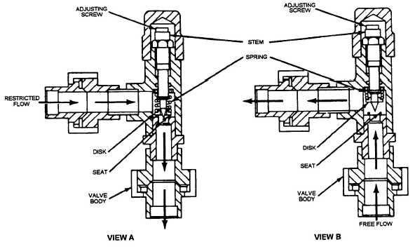
which controls the reaction time of the fuel valve. This
is done by restricting fuel flow through the needle
valve and disk assembly. Flow in the opposite direction
lifts the disk up off the seat, permitting free flow.
Operation of the Cla-Val
A step-by-step analysis of the valve’s operation is
as follows. Figure 5-9 shows the valve in the fueling
position.
1. The solenoid is energized.
2. The SOPV directs pressure from the main valve
inlet into the cover chamber of the defueling valve,
holding it closed.
3. The SOPV also vents the cover chamber of the
hytrol valve to the defueling line. This permits the
pressure-reducing control valve to take over control of
the fueling valve.
4. When the pressure-reducing control valve goes
into operation, high pressure fuel enters the fueling
valve and bypasses through the ejector-strainer to the
pressure-reducing control valve, which is held open by
its compression spring. With pressure at the pressure-
reducing control valve below the adjusted setting, a
maximum flow is permitted through the ejector-
strainer. This creates a reduced pressure in the main
valve cover chamber, which allows the fueling valve to
open to build up pressure in the downstream system.
The increasing downstream pressure is transmitted
through the pressure reducing control valve line to the
under side of the pressure reducing control valve dia-
phragm.
Figure 5-8.—Flow control valve (needle valve).
5-5


