of the pump are enclosed by bearing covers. The bearing
covers prevent bearing grease from leaking out of the
bearing cartridges. In addition, the bearing covers prevent
dirt and water, or fuel from entering the bearing cartridges.
The outside ends of the bearing cartridges are enclosed by
bearing caps. A grease cup and a grease fitting are installed
on both of the bearing caps to allow addition of grease to
the bearings. Grease reliefs are also installed to release
grease during heat expansion.
Flexible Coupling. —The flexible coupling is
designed to allow for misalignment between the motor shaft
and the pump shaft. The coupling hubs are keyed to both
the pump and motor shafts and are lubricated to reduce
wear in the coupling.
THEORY OF OPERATION. —The spinning
impeller causes fuel to leave the discharge chamber of the
pump. This creates a suction that causes a continuous flow
of fuel to the pump. Fuel from the service tank
simultaneously replenishes the fuel that leaves the suction
chamber as long as the pump has a positive suction head.
Centrifugal pumps WILL NOT draw a vacuum. Fuel in the
suction chamber enters the center part of the impeller. The
blades of the impeller propel the fuel toward the discharge
chamber walls by centrifugal force. The expanding spiral
shape of the discharge chamber slows the fuel which
increases the pressure and creates a continuous flow
through the pump. Flow is continuous as long as there is
enough fuel at the suction side, air does not enter the pump,
fuel discharge is not restricted, and the impeller rotates at
the rated speed.
MAINTENANCE. —Maintenance on the JP-5
centrifugal service pump is done in accordance with PMS
and the applicable technical manuals. Typical maintenance
is discussed in the following paragraphs.
LUBRICATION. —The importance of proper
lubrication of the ball bearings cannot be over-
emphasized. But, it is possible to over-grease the
bearings, which causes overheating and damage to the
bearings. Additionally, the wearing rings and mechanical
seals require JP-5 for lubrication. Running the pump dry
will damage these parts.
WEARING RINGS. —Wearing rings should be
inspected when the pump does not discharge at the rated
capacity. They are replaced when the radial clearance stated
in the pump’s technical manual is reached.
MECHANICAL SEALS. —Mechanical seals require
no maintenance, but should be replaced whenever leakage
occurs, or when the sealing surfaces have been disturbed.
TROUBLESHOOTING. —Table 4-2 lists typical
malfunctions, probable causes, and corrective action for the
JP-5 service pump.
Rotary Vane
Blackmer is the most commonly used rotary vane
pump in the JP-5 below decks system. These pumps come
in different sizes with different operating capacities and are
used as transfer pumps, auxiliary pumps, stripping pumps,
and on the flight deck as defuel pumps. Each pump may
vary slightly, but all are practically identical.
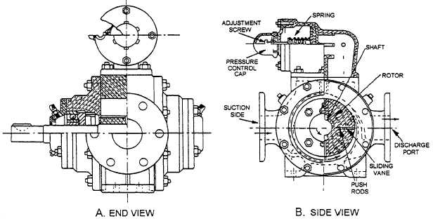
The Blackmer (fig. 4-10) is a positive displacement,
rotary vane type pump. The pumps used for stripping are
designed to pump 50 gpm at 50 psi. The pumps used
Figure 4-10.—Blackmer rotary vane pump: A. (End view); B. (Side view).
4-13