Lovejoy Coupling
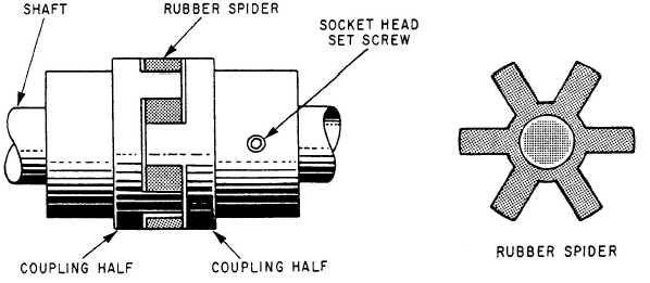
The Lovejoy coupling (fig. 4-13) mechanically
links the shaft of the pump to the shaft of the motor
(or gear reducer). The coupling is made of two bronze
coupling halves. The coupling is keyed to the shaft
and held in place by socket-head setscrews. The
coupling halves are cushioned by a formed rubber
spider that separates the coupling halves. This
rubber separation reduces wear on the coupling
halves.
When the reassembly of any component of the
pump unit involves re-coupling, the coupling should
be checked for misalignment using a straightedge
and feeler gage. As different pumps have different
size couplings that require different clearances,
consult the specific pump technical manual for proper
clearance of your specific coupling. When adjusting
the couplings, make sure each section of the coupling
is tightly anchored to its respective shaft and that
both sections are butted together with the correct
space (according to the specifications in the technical
manual) between the coupling sections and the
rubber spider. The Lovejoy coupling requires no
lubrication.
Rex Chain Coupling
The Rex chain coupling mechanically links the
shaft of the pump with the gear reducers on motor
driven stripping pumps. Each shaft has a toothed
gear attached and, when both shafts are aligned, a
chain is placed around both gears, connecting both
halves. It resembles small bicycle sprockets placed
side by side with a double wide chain connecting the
two.
Although periodic inspection and lubrication are
required, the main advantage is its ease of removal
and alignment. The gears and chain are steel and can
break if hit with a hammer. Therefore, do NOT use
force. When installing a Rex chain coupling, if you
feel force is needed, you are doing something wrong.
VALVES
Several types of valves are used in the JP-5 sys-
tems. Typically, the valves used in the filling and
transfer system are of the gate type. Most discharge
valves on pumps are of the globe type. Distribution
piping may contain gate, globe or butterfly. Newer
ships may have limitorque valve operators in their
system. In the following paragraphs, we will discuss
the various type valves, their description and con-
struction, and their normal use. Know the type of
valves in your system and their location.
Gate Valves
A gate valve (fig. 4-14) is used where a straight
flow with a minimum amount of restriction is desired.
Figure 4-13.—Lovejoy coupling.
4-18


