for transfer are designed to pump 200 gpm at 50 psi.
The typical rotary vane pump consists of a cylinder
and head assembly, rotor and shaft assembly, and a
pressure control valve.
CYLINDER AND HEAD ASSEMBLY. —The
cylinder (pump casing) houses and provides a
working area for the rotor and shaft assembly. The
cylinder is machined to form an egg-shaped cylinder
bore. The inlet and discharge ports are cast integrally
with this section of the pump. The pressure control
valve, located on the top of the pump, is cast
integrally with the upper portion of the cylinder bore.
Each side of the cylinder has machined recesses to
ensure perfect fit of the cylinder heads.
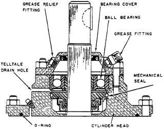
The cylinder heads (fig. 4-1 1), one for each side
of the pump, house the ball bearings and mechanical
seals. An O-ring is installed between the cylinder
heads and the cylinder to prevent leakage.
The ball bearings, located in the bearing housing
within each cylinder head, support and ensure free
rotation of the rotor and shaft assembly, and
maintain the proper clearance between the rotor and
upper position of the cylinder bore. A bearing cover,
with a grease fitting at the top and a grease relief
fitting at the bottom, is bolted to the end of each
cylinder head.
The mechanical seal installed in each head pre-
vents leakage of fluid along the shaft into the bearing
housing. A telltale drain hole, located directly under
the bearing housing, is provided on the underside of
each head. These holes are intended to serve as an
indication of leakage by the mechanical seal.
Figure 4-11.—Rotary vane pump cylinder head.
ROTOR AND SHAFT ASSEMBLY. —The rotor
and shaft is a pressed fit assembly held in place by
tapered pins. The rotor is centered in the upper
portion of the oval shaped cylinder bore. The rotor
has an even number of equally spaced slots that
provide the working area for the sliding vanes. Holes
are drilled through the rotor and shaft, one between
each set of opposing slots, for the installation and
working area of the push rods.
The sliding vanes are made of palamite. Relief
grooves are provided on the forward face of the vanes
to allow the escape of liquid trapped between the
vanes and the slots in the rotor.
NOTE
The vanes must face the direction of
rotation to allow the escape of fluids into the
discharge port.
The pump shaft connects to a gear reducer shaft
by a flexible coupling. The opposite shaft of the gear
reducer is connected to the shaft of the drive motor,
also by a flexible coupling. The purpose of the gear
reducer is to mechanically reduce the motor rpm to
match the rated rpm of the pump.
PRESSURE CONTROL VALVE. —The pres-
sure control valve is provided to prevent buildup of
excessive pressure that might damage the pump or
associated equipment. When over-pressurization
occurs, the valve directs fluid from the discharge side
to the suction side of the pump. It is spring-loaded
closed. An adjustment screw adjusts spring tension
on the valve disc. Relief pressure is determined based
on pump application and piping design. The
adjustment screw has a locknut to lock it at the set
pressure. The pressure control cap is screwed on the
cover to protect the adjustment screw threads.
THEORY OF OPERATION. —The rapid
rotation of the shaft and rotor forces the vanes in
sliding contact with the cylinder bore by centrifugal
force and by push rods. The passage of the vanes
through the lower portion of the cylinder bore draws
fluid into the pump, and at the same time, forces it
out the discharge port. Rotary vane pumps are
positive displacement pumps. This means they will
pump air, which creates a vacuum, causing liquid to
be pulled into the suction side of the pump.
MAINTENANCE. —Maintenance on the rotary
vane pump is done in accordance with PMS and the
4-15


