
Figure 2-17.-Connector soldering sequence.
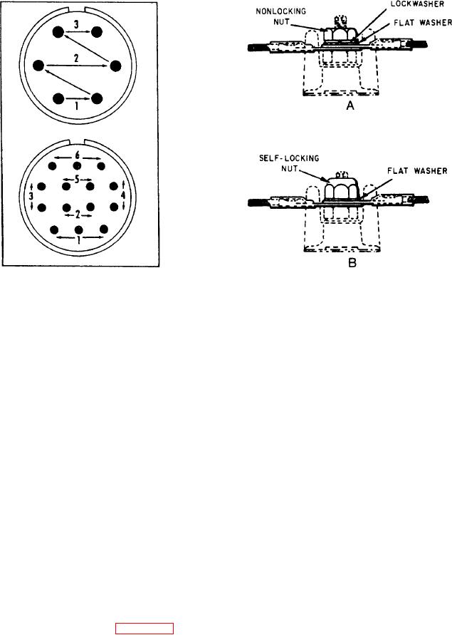
Figure 2-18.-Installation of cable terminals on terminal
block.
connectors in wheel wells, wing fold areas, engine
areas, engine nacelles, or cockpit decks have a
is especially desirable in areas of high vibration.
high chance of failure and are sealed. In addition,
In both installations, a requirement exists for the
moistureproof all connectors that interconnect
use of a flat washer, as shown in the drawing.
flight/basic navigation equipment.
Vibration and lateral pressure fatigue wires
Each terminal board in the aircraft electrical
system is identified by the letters TB followed by
at the solder cup. Moistureproofing reduces
the number of the individual board. Each stud
electrical connector failures by reinforcing the
wires against vibration and lateral pressure.
on the terminal board is identified by a number.
The sealing compound also protects electrical
The lowest number in the series starts at the end
nearest the terminal board identification number.
connectors from corrosion and contamination by
The identification number is on the structure to
excluding metallic particles, water moisture, and
which the terminal board attaches. It mounts on
aircraft liquids. One result of the connector's
better dielectric characteristics is the reduced
any identification strip cemented to the structure
chance of arc-over between pins.
under the terminal board. When replacing a
terminal board, don't remove the identifica-
TERMINAL BLOCKS
tion marking. If the identification marking is
damaged, replace it with one that is the same as
Terminal blocks, made from an insulating
the original.
material, support and insulate a series of terminals
from each other, as well as from ground. They
provide a way to install terminals within junction
JUNCTION BOXES
boxes and distribution panels.
The two methods of attaching cable terminals
Junction boxes accommodate electrical
terminals or other equipment. Individual junction
to terminal blocks are shown in figure 2-18. View
boxes are named according to their function,
A uses a standard nonlocking nut. In this
location, or equipment with which they are
installation method, the use of a lockwasher is
associated. Junction boxes have a drain hole
necessary. View B shows the preferred method.
(except boxes labeled "vaportight") at the lowest
When using an anchor nut, or self-locking nut,
point to drain water, oil, condensate, or other
you omit the lockwasher. The use of anchor nuts