
and systems test logic. Figure 6-14 shows inputs
115-volt ac, 400-hertz power. This functions. Notice
power. This power is from essential bus number to
in figure 6-14 that the CADC power is also from
the CADC and the CADC outputs to the 2 (phases
one phase of the essential bus system uses three-
A, B, and C). The system also uses systems, which
phase, 115-volt ac, 400-hertz and goes to the
depend on or in part upon CADC single-phase,
backup channel. Cooling
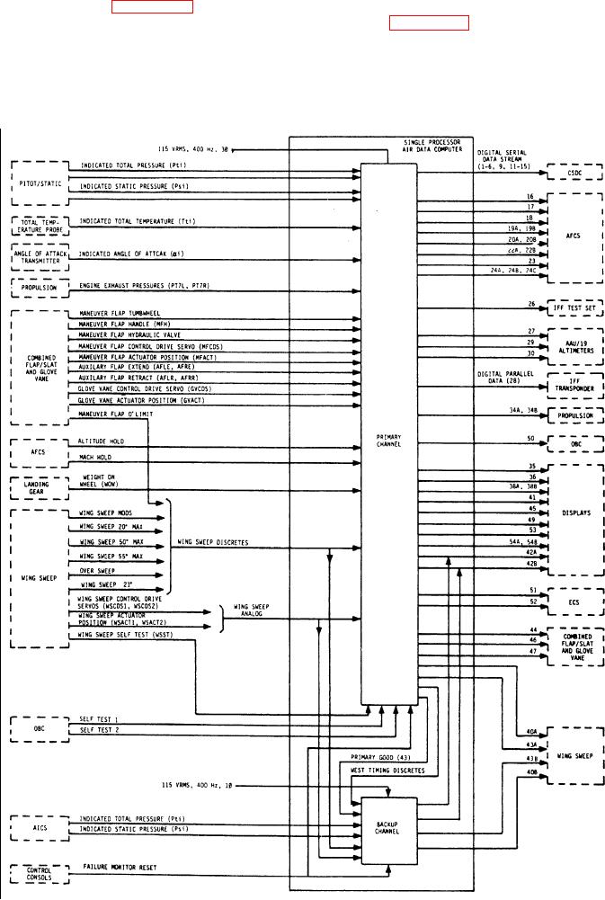
Figure 6-14.-Air data computer block diagram showing inputs and outputs.
6-12