
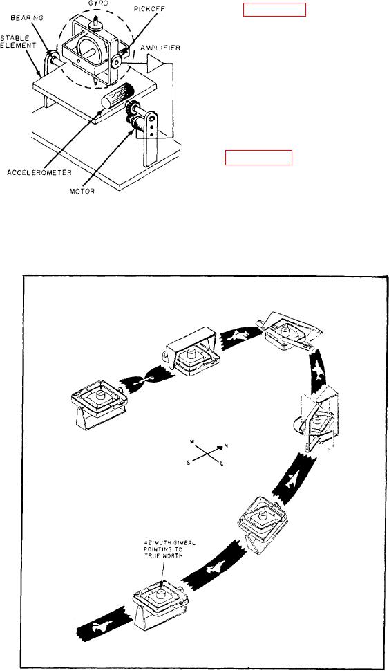
Figure 7-37 shows a two-degree-of-freedom
gyro and a single-axis stable platform. The
pickoffs on the gimbals within the gyro produce
electrical signals. These signals occur when the
gyro case moves from its null position with respect
to the gyro motor. The electrical pickoffs will
sense any displacement of the stable element from
the frame of reference. The signals thus created
drive the platform gimbals to realign the stable
element.
PLATFORM GIMBAL STRUCTURE. --
Figure 7-36 shows the four-gimbal platform
configuration actually used in an inertial naviga-
tion system. The stable element mounts in the
gimbal structure so that, regardless of aircraft
maneuvers, it retains the original orientation. The
Figure 7-37.-Single-axis, gyrostablized platform.
stable element serves as a level mount for the
Figure 7-38.-Gimbal flipping action.
7-30