
vehicle and gravitational acceleration. Therefore,
if the accelerometer tilts off level, its output
includes a component of gravitational accelera-
tion as well as vehicle acceleration. Look at
figure 7-33, view C. To get the correct vehicle
acceleration in the horizontal plane, hold the
sensitive axis of the accelerometer normal
to the gravitational field. Refer to figure 7-33,
view B.
The accelerometer mounts on a platform
(stable element) in a way that it is always level.
In this position the accelerometer measures true
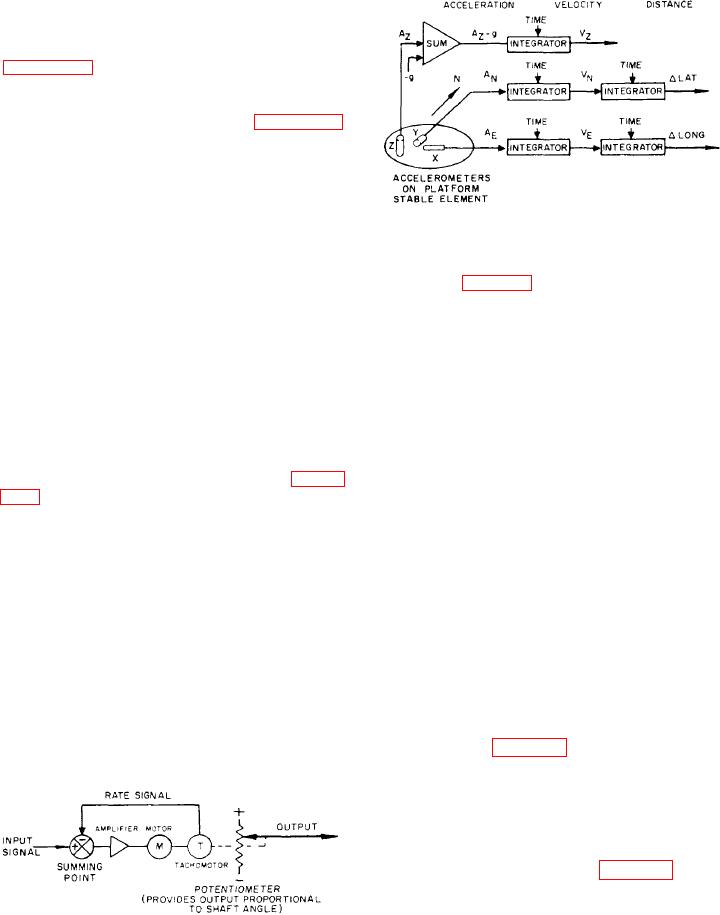
Figure 7-35.-Basic inertial navigation system.
aircraft acceleration in a horizontal direction
along its sensitive axis. Mounting another level
accelerometer perpendicular to the first one gives
integrators (fig. 7-35), the system can determine
you the x and y axes. The system can now
distance traveled in the north-south and east-
determine total true acceleration in a horizontal
plane for any movement in any direction.
west directions. It is important to maintain
the proper accelerometer pointed north and
maintain both accelerometers horizontal to the
Integrators
earth's surface. If the accelerometers tilt off
level, it measures gravitational components,
which results in navigation errors. A third
To convert the measured acceleration to
accelerometer sometimes mounts on the stable
aircraft position information, the system processes
the acceleration signals to produce velocity
element in the vertical plane to determine
vertical acceleration. The computer subtracts
information. It must then process the velocity
information to derive distance traveled. Figure
the gravity component from the output of
7-34 shows an analog type integrator. It is an
the accelerometer. The resulting signal represents
actual aircraft vertical acceleration. A vertical
electromechanical device that receives electrical
acceleration signal goes to an integrator in
input (acceleration or velocity) and produces a
the attitude computer. This computer computes
shaft speed proportional to the input. The
vertical velocity.
shaft angle is the output of the integrator,
and it is the mathematical integral of the
input. If the input is acceleration, the output
Platform Stable Element
is velocity; if the input is velocity, the output is
distance.
To maintain the proper orientation of
the accelerometers, they mount on a stable
If one of the horizontal accelerometers points
north, the other one will always point east.
element together with gyroscopes. The gyro-
By connecting the accelerometer outputs to
scopes are the sensing elements for controlling
the orientation of the stable element. The
stable element (fig. 7-36) mounts on gimbals,
which isolate it from angular motions of the
aircraft.
GYROSCOPES. --The stable element con-
tains two identical, floated, two-degree-of-freedom
gyroscopes. They mount one on top of the other
in a dumbbell configuration (fig. 7-36). The
gyroscopes have their spin axes horizontal and at
right angles to each other. The wheels in these
gyroscopes, which spin at high speed, resist any
effort to change the orientation of their spin
axes.
Figure 7-34.-Analog integrating device.