
integrator produces an output. The second
Look at the velocity curve for the time
integrator ceases to produce an output when the
first integrator (velocity) ceases to produce an
obtained when acceleration is integrated over the
output. The velocity integrator continues to
same interval. The velocity curve is the output of
produce until receiving an acceleration that
interval t o to t1, velocity is changing in an
balances out the initial acceleration. At this point,
it produces a net acceleration of zero. The readout
increasing or positive direction. This means that
device stops at the point where the net accelera-
a positive acceleration is taking place. Velocity is
tion is zero. Until reaching this condition, the
constant during interval tl to t2, which means
readout device shows a continuous change in
acceleration is zero. At time t2, velocity begins
to decrease. This says that an acceleration is again
displacement.
The return trip is described as follows. The
taking place. In this case the acceleration is
train is at point B during time interval t3 to t4;
negative. At time t3, both acceleration and
it begins traveling backwards to point A at time
velocity are zero.
t4. The acceleration detector senses an accelera-
tion a2, which is negative and slightly less than
The purpose of an INS is to keep track of
the previous acceleration, a1. At time t5 i t
position and not total distance traveled. To do
reaches a steady velocity, and acceleration goes
this it integrates all values of acceleration (positive
to zero at this point. Note that velocity is now
and negative) detected over the interval. There-
negative since the direction of travel is reversed.
fore, it is the net value of acceleration that
Since the size of acceleration a2 is less than that
interests the INS. For instance, in the interval to
of al, maximum velocity on the return trip is less.
to t3, all accelerations that occur over the
Therefore, the time required to return to point
interval are summed, giving a net value at time
A is greater. Interval to to t7, greater than time
interval to to t3 reflects this fact. The train begins
7-28, view A) is the process of summing the area
to stop within a short distance of point A. This
bounded by the acceleration curve and the time
happens at time t6, producing an acceleration of
axis. The area above the time axis is positive,
a2 as sensed by the acceleration detector. The train
and the area below the time axis is negative. Since
comes to a full stop at time t7. Here the detector
the areas above and below the time axis are equal,
senses zero acceleration. Since the net accelera-
the net value for interval to to t3 acceleration is
tion over the interval is again zero, the output of
zero. The integral of acceleration for the interval
the first integrator (velocity) is zero. The second
to to t3 is therefore zero. This means that the
integrator (displacement) output stops with the
velocity at time t3 is equal to the velocity at time
displacement readout device showing the reference
to, in this case zero.
value. This value is the same originally noted at
Integrating velocity from time tO to t3 i s
reference point A.
The simple single-axis INS just described will
the job of the second integrator. It gives
detect and compute all changes in displacement.
B units of displacement on the displacement axis
However, the acceleration detector (accelerometer)
at time t3. The displacement readout device
must retain its straight-line orientation. Also, all
changes continuously as long as the second
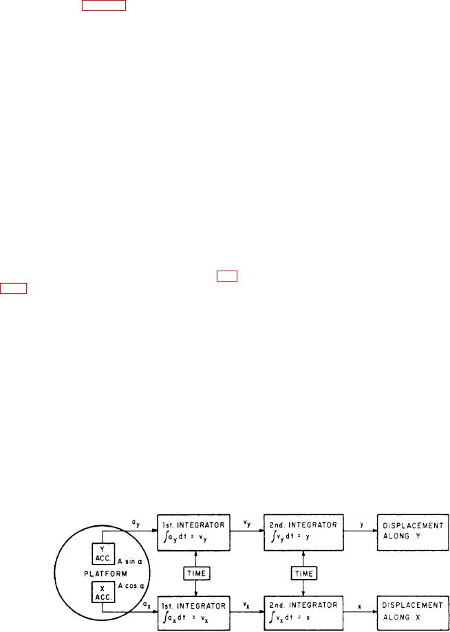
Figure 7-29.-Two-axis inertial navigation system, block diagram.
7-24