
from a resolver in the compass controller. The
EARTH RATE CAL variable resistor in the
compass adapter adjusts this signal. Real drift
is caused by mechanical imperfections in
construction of the directional gyroscope. The
compensating signal for real drift develops across
the compass adapter GYRO DRIFT COMPEN-
SATION POT variable resistor. This resistor has
a dial calibrated in degrees per hour. The corrected
information goes to external aircraft system com-
ponents through five heading repeater synchros.
When operating in the compass mode, the
24-point compensation network corrects the flux
valve signal for deviations. This signal goes as an
error signal to the azimuth servo loop, resulting
Figure 7-23.-Compass adapter compensator.
in corrected azimuth information (angle data
shaft). Again, this information goes to external
aircraft system components through five heading
drive the displacement gyroscope roll and pitch
repeater synchros.
gimbals.
In the slaved mode, the directional gyroscope
Two thermal relays and nine control relays
azimuth information and a compensated flux
perform the timing and switching required for the
valve heading correction signal go to a differential
start cycle. The start cycle is of 60 seconds
synchro in the compass adapter. This slaves or
duration. However, certain conditions change
synchronizes the gyroscope azimuth output to the
after the first 12 seconds. High pitch erection
flux valve heading, providing a heading output
voltage goes to the pitch torquer for the complete
rather than a displacement output. Fast syn-
start cycle. High roll erection voltage goes to the
chronization starts when the slaved mode is
roll torquer after 12 seconds and continues until
selected and is maintained until close alignment
the completion of the start cycle. After the first
is achieved. Slow synchronization is applied
12 seconds, motor excitation voltage increases,
continuously while operating in the slaved mode.
and the gyroscope motors attain operating speed.
After completion of the start cycle, two additional
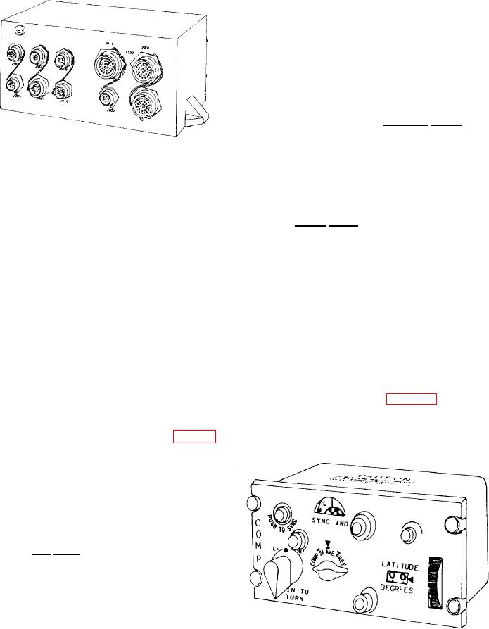
Compass Controller
relays provide roll and pitch erection cutout
during specific aircraft maneuvers.
The compass controller (fig. 7-24) provides
switching functions, latitude compensation
Compass Adapter Compensator
signals, and slew signals to the system compass
The compass adapter compensator (fig. 7-23)
receives heading information from the flux valve
and the displacement gyroscope. It processes this
information according to the azimuth mode
selected by the compass controller. It then
provides corrected heading signals to the heading
indicator and other aircraft systems. The compass
adapter compensator can operate in the following
modes: free, compass, and slaved.
In the free mode of operation, you engage the
PUSH TO TURN control on the compass
cent roller to set actual aircraft heading. This
establishes an initial azimuth reference. As air-
craft heading changes, an azimuth synchro on the
directional gyro measures the relative change
between the aircraft and the directional gyroscope.
The signal goes to the compass adapter, which
makes corrections for real and apparent drift. The
Figure 7-24.-Compass controller.
compensating signal for apparent drift is derived