
adapter. The compass controller also monitors
and provides a visual display of the synchroniza-
tion between the azimuth heading output and the
flux valve.
The compass controller can operate in three
modes--slaved, free, and compass. The compass
controller contains a PUSH TO SYNC switch and
SYNC IND meter. It also has a PUSH TO TURN
control, mode switch (with COMP, SLAVE and
FREE positions), and LATITUDE DEGREES
control (counter assembly).
The mode switch selects the FREE (free),
SLAVE (slaved), and COMP (compass) modes
of operation. To accomplish this, it controls the
Figure 7-25.-Switching rate gyroscope.
mode-selecting relays in the system compass
adapter. The mode switch also activates the SYNC
IND meter during compass and slaved modes.
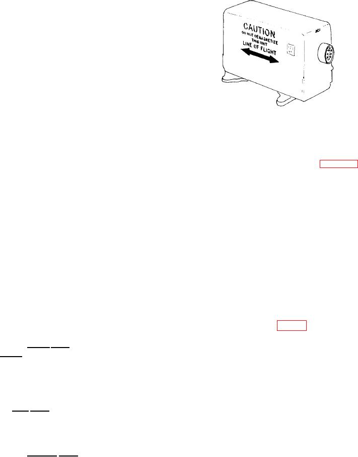
Rate Gyroscope
The PUSH TO TURN control (set heading)
provides switching to decouple the autopilot.
The switching rate gyroscope (fig. 7-25)
Also, it controls the direction and rate of
provides a means of interrupting the roll
slewing for alignment of the system to an azimuth
erection and slaving voltage. It is a single-
heading. This switching action occurs when
d e g r e e - o f - f r e e d o m gyroscope. It provides
using the PUSH TO TURN control to reference
gyroscope sensitivity to rates of rotation about
the system output to the aircraft heading in the
free mode.
the yaw axis of the aircraft. When the air-
The PUSH TO SYNC switch provides switch-
craft turns at rates of 150 per minute or
ing to synchronize azimuth heading output
greater, the gyroscope precesses away from
the normal condition. This causes the contacts
to the flux valve when operating in the slaved
mode.
of a magnetic reed switch to close, energizing
The LATITUDE DEGREES control, working
a single-stage amplifier. Transistor switching
with a resolver, provides a compensation signal
action pulls in a relay, completing the 28-volt dc
for apparent drift of the directional gyroscope.
path to the turn cutout relay coil in the compass
adapter.
Apparent drift results from earth rotation.
The hemisphere switch (N,S) selects the
latitude correction signal for the Northern or
Attitude Indicator
Southern Hemisphere.
The SYNC IND meter shows the synchroniza-
The attitude indicator (fig. 7-26) is a three-axis,
tion between the azimuth heading output and the
flux valve.
servo-driven sphere that shows heading and
relative roll and pitch attitude of aircraft.
The slaved mode is the normal operating mode
Vertical and horizontal pointers provide the pilot
except when in an area where the earth's magnetic
with aircraft deviation information from a desired
field is distorted. The slaved mode synchronizes
flight path. Signals for operating servo systems
the directional gyroscope output to the flux valve
of hermetically sealed units are from the displace-
heading. When initiating the slaved mode, fast
ment gyroscope. Aircraft rate of turn informa-
synchronization occurs until close alignment with
the flux valve heading is achieved.
tion and vertical displacement deviations from a
Free mode is an alternate mode of operation.
desired glide path are displayed by a rate of turn
It is used in areas where the earth's magnetic field
pointer and displacement pointer, respectively.
is distorted. When operating in the free mode,
Loss of ac power is indicated by a display of a
power failure warning flag. Inadequate current
only the directional gyroscope output drives the
system's azimuth indicators.
to vertical, horizontal, and displacement pointers
results in display of respective warning flags. A
The compass mode is an emergency mode for
use when the directional gyroscope fails. Only the
pitch trim knob lets you adjust the sphere to
flux valve output (compensated) provides heading
varying aircraft configurations and reduce
parallax error.
information.
7-20