
Figure 7-27.-Simple single-axis INS block diagram.
Remember from elementary physics that
acceleration, whose units are ft/sec2, multiplied
by time in seconds is velocity in ft/sec. Also, that
velocity (ft/sec) multiplied by time (sec) is
displacement (ft). The integration of acceleration,
for example, is the mathematical process of
summing all minute acceleration-time increments
over a given period. The result of the integration
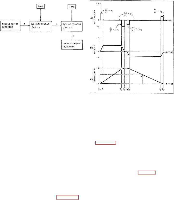
Figure 7-28.-Integration of acceleration and velocity:
of acceleration is velocity over the same period.
(A) acceleration, (B) velocity, (C) displacement.
The same integration process performed on
velocity gives displacement or distance traveled
over the same period.
train returns to point A by traveling backwards.
Thus, the simple inertial device is not disoriented.
At point A the readout device shows the value that
Simple Single-Axis Inertial
was chosen as a reference. This is the displace-
Navigation System
ment at point B minus the distance traveled from
point B to point A.
An example of how a simple single-axis INS
Figure 7-28, view A, is a graph of the detected
operates is illustrated as follows: Assume a
acceleration. View B is the velocity curve obtained
person is on an INS-equipped train on railroad
by integrating the acceleration curve shown in
tracks at the equator. The tracks run in a straight
view A. View C is the displacement curve obtained
line east and west only, The INS consists of an
by integrating the velocity curve shown in view
acceleration detecting device (accelerometer), an
B. All three curves are plotted as a function of
integrating device, and a displacement readout
time.
device. The accelerometer can sense movement in
The acceleration curve (fig. 7-28, view A)
only one direction, along its sensitive axis. The
begins at time to as the train begins to travel from
sensitive axis is an imaginary line parallel to the
point A. Look at view C. The acceleration at time
movement of the mass within the detecting device.
to has a value of al, and it remains at that value
The acceleration detecting device is oriented in the
until t1. At t1 the train ceases to accelerate.
train so that it detects accelerations when the train
Therefore, acceleration goes to zero. At this point,
is moving forward or backward. Figure 7-27 is
the train reaches a steady velocity. The train
a block diagram of such a device.
continues traveling at a constant velocity until
If the train starts moving at point A, you will
time t2 where the train begins to stop. The
note a specific reading on the displacement
acceleration detector detects an acceleration equal
readout device. When the train reaches point B
in value to a1, but its direction is opposite. This
and stops, the readout device will show the new
position. The distance traveled from point A to
now stationary and standing at its destination--
point B added to the reference value noted at point
A will show on the displacement indicator. The
point B.