
(except the earth's motion in orbit around the
sun). Once you accomplish these corrections, you
may navigate on the earth by inertial means. The
earth's motion about the sun does not affect an
earth inertial navigation system. This motion is
translational, and it is equal at all points on the
earth.
BASIC SYSTEM COMPONENTS
The inertial navigation system continuously
measures aircraft accelerations to compute
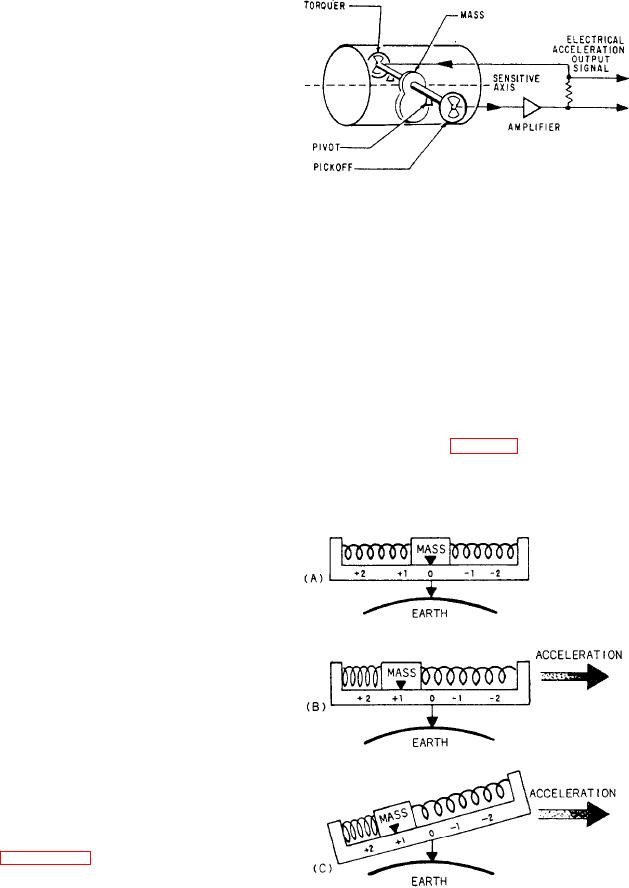
Figure 7-32.-Typical torque-balanced accelerometer.
aircraft velocity and change in present position.
These measurements are made by precision
which causes a torquer to restrain the pendulum.
inertial devices mounted on a three-axis stable
The pickoff signal goes to a high gain amplifier.
element, which is part of a four-gimbal structure.
The four-gimbal structure allows the stable
The output of the amplifier connects to the
element to move with 360 degrees of freedom
torquer on the accelerometer. During an accelera-
tion, this feedback loop sends a voltage to the
about the three axes.
torquer. This voltage holds the pickoff signal
Two gyros provide gimbal stabilization signals
at a null under the influence of the measured
to maintain the stable element level with the
acceleration. This voltage is proportional to the
earth's surface and aligned to true north. Also,
measured acceleration. It also provides the
the system uses these signals to measure aircraft
electrical output acceleration signal that goes to
pitch-and-roll attitudes. The inertial characteristics
the computer.
of the gyroscopes used in the system define and
The accelerometer (fig. 7-33, view A) cannot
maintain the reference axes for relatively long
distinguish between the acceleration of the
periods with great accuracy. With a gyrostabilized
platform as a reference, it is possible to
accurately detect components of motion in
any direction. To do this, precision accelerometers
and analog or digital computers are used in an
INS.
Accelerometers
The primary data source for the inertial
navigation system is the accelerometer. Three
accelerometers are mounted on the stable element
between the gyros. They provide output signals
proportional to total accelerations experienced
along the three axes of the stable element. The
system uses these accelerations to produce aircraft
velocities and changes in position.
An accelerometer consists of a pendulous mass
that is free to rotate about a pivot axis in the
instrument. Figure 7-32 shows one form of this
device. It has an electrical pickoff that converts
the rotation of the mass about the pivot axis to
an output signal. An acceleration of the device
Figure 7-33.-Principle of an accelerometer: (A) acceler-
to the right causes the pendulum to swing to the
ometer at null, (B) true acceleration, (C) spurious
acceleration due to gravity.
left. This provides an electrical pickoff signal,