
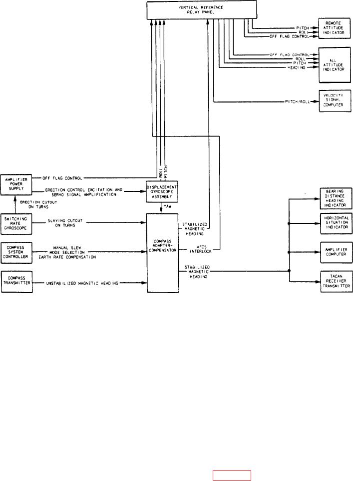
Figure 7-20.-Block diagram of the attitude heading reference system.
Electrical inputs for the compass card and
1,000 flag to place the numeral 1 preceding the
hundreds numeral. This enables the counter to
pointers come from synchro transmitters located
in other equipment. In the ID-663A/U, synchro
display distance up to 1,999 nautical miles.
torque receivers position the compass card and
The OFF flag covers the distance counter
both pointers, In the ID-663 B/U and ID-663B/V,
when distance information is not available. In
torque receivers position both pointers. These
the ID-663B/V, the 1,000 flag and OFF flag are
torque receivers contain a synchro control
positioned by separate coils, The ID-663A/U,
transformer, a transistor error signal amplifier,
ID-663B/U, and ID-663 C/U have a meter-type
and a two-phase servomotor to position the
movement, which, when de-energized, shows
compass card. In the ID-663C/U, the control
OFF. Partial rotation moves the OFF flag out of
transformer-amplifier srvomotor positions the
view, and full rotation brings the 1,000 flag into
compass card and both pointers.
view.
The distance counter may display distance
ATTITUDE HEADING
to base, target, or ground electronic station,
REFERENCE SYSTEM (AHRS)
depending on the mode selected. It consists of
The AN/ASN-50 attitude heading reference
units, tens, and hundred numerals. It also has a
system (fig. 7-20) generates and provides