
again concentrate in the core. However, they are
not moving, so the induced voltage in the
secondary coils is zero.
The same action takes place during the
negative half of the 400-hertz excitation current.
This makes the resulting output of the flux valve
an 800-hertz signal. The voltages of each of the
three secondary coils pass through zero at the
same instant. However, their polarity and
amplitude depend on the heading of the aircraft.
They vary in the same fashion as the stators of
a synchro transmitter. This would allow you to
use it to drive an 800-hertz synchro system.
The original 400-hertz excitation is effectively
cancelled by the special construction of the metal
core and windings. This construction allows lines
of flux produced by the primary coil to induce
canceling voltages in the secondary coils.
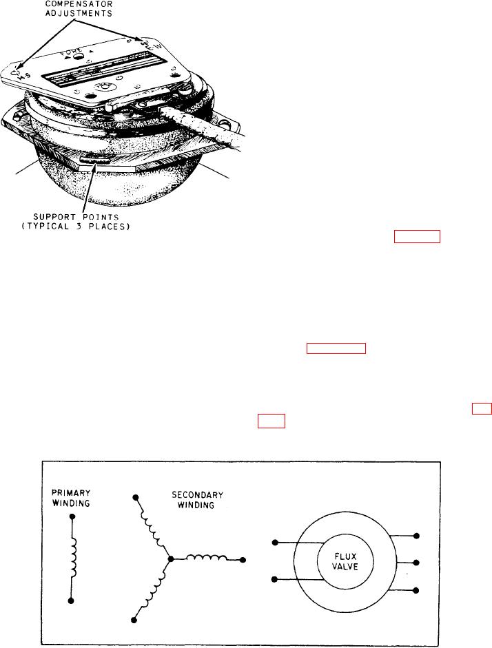
Attached to the top of the compass transmitter
is a compensator assembly (fig. 7-15). It consists
primarily of two sets of two small permanent bar
Figure 7-15.-Compass transmitter and compensator.
magnets. You can change the relative azimuth
position of each set by rotating a screw on the
outside of the unit. These screws position the
The movement of flux lines increases until point
magnets by a gear train. One adjusting screw
Y on the 400-hertz sine wave, and then the
adjusts for north-south compensation, and the
movement tapers off and stops moving at point
Z. At this point no voltage is induced into the
other screw adjusts for east-west compensation.
secondary winding. As the primary sine wave
Two wiring symbols for the flux valve are
shown in figure 7-16. To distinguish them from
synchro units, the words compass transmitter or
core decreases. The core now attracts more and
more of the earth's flux lines. These lines of flux
flux valve are usually included in the drawing.
cut through the secondary coil in the opposite
Displacement Gyroscope Assembly
direction and induce a voltage of the opposite
The displacement gyroscope assembly (fig.
polarity. When the primary sine wave reaches X1,
7-17) consists of a vertical gyro (VG) and a
the maximum number of the earth's flux lines
Figure 7-16.-Compass transmitter schematic and functional symbols.