
Figure 7-13.-Magnetic flux line movement.
indicators, and other components. Also, by
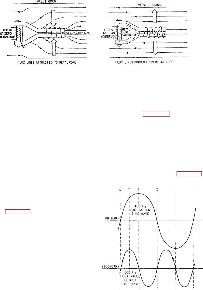
magnetic field changes the reluctance of the core.
using these signals, indicators can include aircraft
When the 400-hertz ac goes to the primary coil,
heading along with other information in a single
the current generates a magnetic field in the core.
instrument.
The magnetic field drives the core to saturation
at the peak of each positive and each negative
Compass Transmitter
portion of the cycle. Figure 7-13 shows the side
The compass transmitter, called a flux valve,
view of the center hub and one leg of the sensing
detects the direction of the flux lines of the
element.
magnetic field of the earth. It electrically sends
When the 400-hertz voltage is at zero, the
this information to a servo loop. The transmitter
reluctance of the core is low. This allows the
is only a few inches in height. It is usually
maximum number of the earth's magnetic flux
mounted within the wing or tail of the aircraft
lines to concentrate in the core. As the primary
as this area has the lowest magnetic disturbances
sine wave builds up toward maximum, reluctance
in the aircraft. It consists of a hermetically
increases, making the core less attractive to earth's
sealed hemispherical bowl containing a pendulous
magnetic flux lines. As the magnetic flux lines
sensing element in a damping fluid. A universal
move out, they cut through the secondary coil and
mounting permits the sensing element up to
induce a voltage (emf) in it. Refer to figure 7-14.
30 degrees of freedom in roll and pitch, while
prohibiting rotation about the vertical axis.
The laminated metal core of the flux valve is
a good conductor of magnetic lines of force (high
permeability). It is shaped like a three-spoked
wheel with the rim split between the spokes, as
shown in figure 7-12. The earth's magnetic lines
of force will concentrate in these legs because they
offer low reluctance to the flux. The amount of
flux in any one leg is proportional to the angular
position of the leg relative to the earth's magnetic
lines of flux. The signal pickup coils are wound
around these legs, one for each leg. The coils are
1200 apart in a horizontal plane. The coils
connect electrically in a wye configuration.
The exciter coil is wound around the hub of
the core, corresponding to the axle of a wheel.
This coil receives 400-hertz ac power. This coil
is the primary, and the signal pickup coil is the
secondary. The design of the core and windings
prevents transformer action between the coils. The
purpose of the primary winding and its applied
voltage is to produce a magnetic field. This
Figure 7-14.-FIux valve sine waves.