
electrolytic switches sense unlevel conditions in
maintained perpendicular to the surface of the
pitch and roll. The output of the electrolytic
earth. The pitch servo control transmitter output,
switches activates the torquers. The gyro reacts
through the pitch servo control transformer, is
to the applied torque and precesses until the
amplified and drives the pitch follow-up motor-
electrolytic switches are level. The inner roll
generator. The motor-generator positions the
control transmitter is mounted between the
directional gyro pitch gimbal.
vertical gyro pitch gimbal and the inner roll
Azimuth Sensing. --The azimuth gimbal may
gimbal. This transmitter applies signals to the roll
settle at any random position in yaw. The only
servo amplifier to drive the roll motor-generator.
forces acting on the gimbal are gyro rigidity,
The roll motor-generator, in turn, drives the outer
apparent (earth rate) precession, and the leveling
roll gimbal to the level of the inner roll gimbal.
torquer. Azimuth sensing in the directional gyro
operating mode is reliable only after setting the
Pitch Sensing. --As the aircraft pitches, the
correct heading into the system with the SET
outer roll gimbal follows, but the vertical gyro
HDG control. Two azimuth control transmitters
pitch gimbal remains level. The pitch servo
sense any movement of the directional gyro pitch
control transmitter detects the pitch attitude and
gimbal about the azimuth gimbal. The yaw signal
applies pitch signals to the indicators and other
of one azimuth control transmitter goes to the
aircraft systems. The pitch control transmitter
attitude indicator. The yaw signal of the other
applies pitch signals to the automatic flight
azimuth control transmitter is processed in the
control system (AFCS) control amplifier.
compass adapter-compensator and applied to
Roll Sensing. --As the aircraft rolls, B101
other aircraft systems.
remains level, but the vertical gyro pitch gimbal
rolls (with the outer roll gimbal). The inner roll
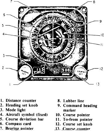
Horizontal Situation Indicator (HSI)
control transmitter senses the difference. It then
Aircraft, such as the P-3, use the horizontal
causes the roll amplifier to drive the roll motor-
situation indicator to provide the pilot with a
generator until the outer roll gimbal is level with
B101. The outer roll control transmitter (on front
end of frame) detects and applies roll signals to
indicators and other systems. The roll control
transmitter (on aft end of frame) applies roll
signals to the AFCS control amplifier.
DIRECTIONAL GYROSCOPE OPERA-
TION. --The directional gyro consists of gyro spin
motor B201 (including a leveling gimbal), an
azimuth gimbal, and a directional gyro pitch
gimbal. The directional gyro pitch gimbal mounts
in the outer roll gimbal. The pitch gimbal may
move 3600 about the pitch axis, but it follows the
outer roll gimbal in roll and yaw. The azimuth
gimbal mounts in the directional gyro pitch
gimbal. It may move 3600 about the yaw axis;
however, it follows the directional gyro pitch
gimbal in pitch and roll. B201 mounts in the
azimuth gimbal. B201 is limited to 85 by
mechanical stops (not shown) to prevent gimbal
lock.
Leveling. --The leveling control transmitter
output goes to the leveling amplifier, which drives
the leveling torquer. When the leveling torquer
moves the azimuth gimbal, B201 precesses until
the leveling control transmitter senses a level
condition. The directional gyro pitch gimbal is
Figure 7-18.-Horizontal situation indicator.
servoed to the vertical gyro pitch gimbal and