Each ASE amplifier module and each of the
yaw synchronizer modules contain a regulated
power supply. Individual ac and dc fuses prevent
failure in one channel from affecting another
channel.
Gain Capsules. --Each module, except the yaw
synchronizer module and the vertical accelerom-
eter amplifier module, contains a plug-in gain
capsule. A gain capsule consists of resistors and
jumpers that determine module gain and signal
path. Since each module has a particular function,
you must be sure the proper gain capsule is
inserted in the amplifier.
ATTITUDE DEMODULATOR. --When the
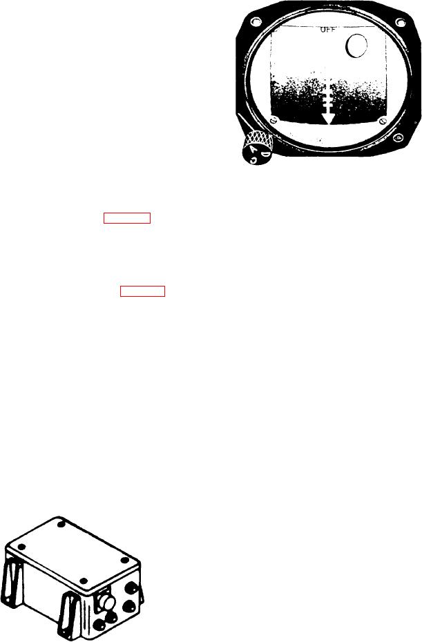
Figure 8-40.-Hover indicator.
ASE is operating in the C mode, the pitch and
roll vertical gyro signals are demodulated by the
attitude amplifier demodulator (fig. 8-39). The dc
indicator, which moves horizontally left or right,
output of the demodulator is compared with the
coinciding with the horizontal scale.
cable angle drift sensor dc voltage. The sum of
There is a mode selector switch on he lower
the two dc voltages goes to the hover indicators.
left edge of the hover indicator case marked with
positions A, C, and D. The hover indicator also
HOVER INDICATOR. --There are two hover
contains a mode selector window on the dial face
indicators on the instrument panel (fig. 8-40). The
that operates with the mode selector switch. One
indicators show Doppler information during
of the letters (A, C, or D) is displayed here to show
automatic cruise flight. During an automatic
the mode of operation.
transition from forward flight to a hover, the
Operation in the A mode connects the hover
indicator displays speed drift and rate of descent.
indicator to ASE. With the meter selector on the
The hover indicator contains scale increment
marks across the center vertical and horizontal
channel monitor panel in ASE position, the hover
axes and along the vertical (left side) and bottom
indicator operates as a null indicator. The hover
of the dial face. Two movable bars coincide with
indicator horizontal bar monitors the pitch
channel. The vertical bar monitors the roll
the center vertical and horizontal axes scale marks
channel; the vertical pointer, the altitude channel.
on the dial. When the aircraft is hovering, these
The horizontal pointer monitors the yaw channel.
bars intersect at a small circle on the face. There
Operation in the D mode connects the hover
are two arrowhead pointers. One pointer is on the
left side of the indicator, which moves vertically
indicator to the Doppler radar. The horizontal bar
shows forward or aft velocities, and the vertical
up or down, coinciding with the vertical scale, The
bar indicates left or right drift. Each increment
other pointer is located at the bottom of the
on the hover indicator horizontal and vertical
scales equals 10 knots ground speed, with a
maximum indication of 40 knots. The vertical
pointer shows vertical velocity, with each incre-
ment equal to 250 feet per minute. Full-scale
deflection is equal to 1,000 feet per minute up or
down. To show forward flight, the horizontal bar
moves downward, To indicate drift, the vertical
bar moves in a direction opposite to the direction
of drift; therefore, the pilot flies into the bar for
correction.
Operation in the C mode connects the hover
indicator to the cable pickoff potentiometers
mounted on the sonar hoist assembly. The
horizontal and vertical bars of the indicator then
Figure 8-39. -Attitude demodulator.
8-41

