
the helicopter moves. By moving the cyclic stick
heading of the helicopter. By pressing the left
in any direction, the pilot causes the tip-path plane
pedal, the pilot causes the rotary rudder blade
of rotation of the rotary wing blades to tilt in that
pitch to increase. This increases blade thrust and
direction. As a result, the helicopter moves in the
turns the helicopter to the left. By pressing the
same direction.
right pedal, the pilot causes the rotary rudder
blade pitch to decrease. This decreases thrust and
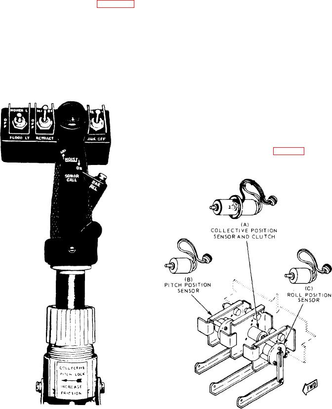
COLLECTIVE PITCH LEVER. --The pilot
lets the rotor torque reaction turn the helicopter
uses the collective pitch lever (fig. 8-44) to
to the right.
change the pitch of all the rotary-wing blades
simultaneously. This angular change is equal on
ASE Sensors
all the main rotor blades. Changing the pitch will
ASE signal voltages for controlling helicopter
increase or decrease the lift accordingly.
movement come from the following sensors and
RUDDER PEDALS. --The pilot uses the
associated components:
rotary rudder pedals to change the pitch and
Collective position sensor and clutch
thrust of the rotary rudder, thus changing the
Pitch-and-roll position sensors
Tilt table
COLLECTIVE POSITION SENSOR AND
CLUTCH. --The electromechanical collective clutch
nulls the collective position sensor (fig. 8-45, view A)
Figure 8-44.-Collective pitch lever grip.
Figure 8-45.-Position sensors.