
PITCH-AND-ROLL POSITION SENSORS. --
output when barometric altitude is disengaged. The
The pitch-and-roll position sensors (fig. 8-45, views B
clutch consists of a stationary coil and self-centering
and C) are identical single-phase, salient-pole,
springs. The input male shaft can rotate continuously
variable-induct ion transformers. The sensor rotor
when disengaged. The output female shaft is spring-
acts as the primary and the stator acts as the
centered and follows, without slip, any input shaft
secondary. The stator is nonsinusoidally wound. The
rotation through a minimum of 45 degrees of rotation.
stator windings are isolated for practically unlimited
The rotation can be in either direction from the 0-
sensor resolution.
degree de-energized position. The clutch has no
As the flight controls mechanically rotate the
common ground between the coil and case and has an
rotor, a signal is produced. This signal is the sensor
output zero rest position repeatability of one-quarter
output required to cancel the vertical gyro signals in
degree.
the
pitch
and
roll
channels.
The
signal
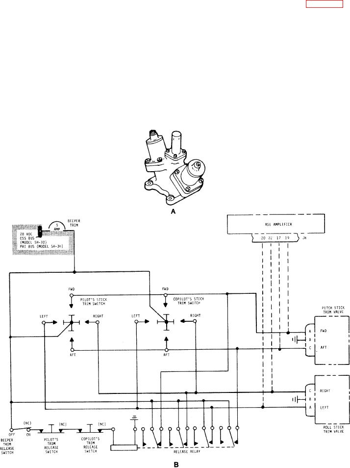
Figure 8-46.-Stick trim valve and schematic diagram.
8-44