
represent cable angle, with each increment equal
to about 2.5 degrees of cable angle. The vertical
pointer shows sonar depth as an error signal. The
null position represents the selected sonar search
altitude. Each increment above and below the null
point represents 10 feet of error.
In both C and D) modes, the yaw pointer is
inoperative and should not move. An OFF flag
on the upper dial face of the hover indicator can
appear in all three modes of operation. In the A
mode, the flag disappears when the ASE is
engaged. In the D mode, the flag disappears when
the Doppler signal is reliable. In the C mode, the
flag disappears when the sonar equipment is
turned on.
Figure 8-42.-Altitude controller.
INERTIAL VELOCITY SYSTEM COM-
PUTER. --The inertial velocity system computer
altitude from a reference altitude and generates
(fig. 8-41) derives separate inertial velocity signals
a voltage proportional to the altitude difference.
for pitch and roll ASE channels during the cable
The excitation voltage and the output voltage will
angle mode of operation. The computer contains
be 180 degrees out of phase at altitudes below the
two separate channels for pitch and roll signals.
established reference. They will be in phase at
It receives inputs from the pitch and roll
altitudes above the established reference.
A purifier chamber lessens the moisture
accelerometers, the vertical gyro, and the Doppler
system.
content in the altitude controller by routing the
ASE operation is controlled by the sonar
airflow through a desiccant cartridge in this
system when the transducer is submerged. The
chamber.
Doppler velocity signals are routed past the
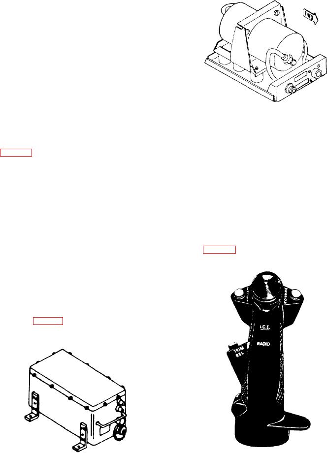
CYCLIC STICK. --The pilot uses the cyclic
inertial velocity signals and then delayed for 40
seconds. The Doppler velocity signals then
stick (fig. 8-43) to control the direction in which
integrate with the accelerometer and vertical gyro
signals, resulting in an inertial velocity signal. This
signal represents both short-term velocity sensed
by the accelerometer and long-term velocity
produced by the delayed Doppler signal.
ALTITUDE CONTROLLER. --The altitude
controller (fig. 8-42) senses changes in barometric
Figure 8-41.-Inertial velocity system computer.
Figure 8-43.-Cyclic stick grip.
8-42