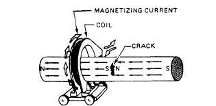
Figure 15-9.—Coil creates a longitudinal field to show crack in
a part.
the part and induce a longitudinal magnetic field.
Inspection of a cylindrical part with longitudinal
magnetism is shown in figure 15-9. If there is a
transverse discontinuity in the part, such as that in the
illustration, small magnetic poles are formed on either
side of the crack. These poles will attract magnetic
particles, forming an indication of the discontinuity.
Compare figure 15-9 with figure 15-5, and note that in
both cases a magnetic field has been induced in the part
that is at right angles to the defect. This is the most
desirable condition for a reliable inspection.
ALTERNATING CURRENT.—The use of alter-
nating current (ac) in magnetic particle inspection is
recommended only for the detection of surface
discontinuities, which comprise the majority of
service-induced defects. Fatigue and stress corrosion
cracks are examples of cracks usually open to the
surface. Alternating current, which must be single phase
when used directly for magnetizing purposes, is taken
from commercial power lines or portable power sources,
and is usually 50 or 60 hertz.
DIRECT CURRENT.—Direct current (dc) mag-
netizes the entire cross section more or less uniformly
in the case of longitudinal magnetization. Magnetic
fields produced by direct current penetrate deeper into
apart than fields produced by alternating current, which
makes it possible to detect subsurface discontinuities.
Generally, direct current is used with wet magnetic
particle methods. In the presence of dc fields, dry
powder particles behave as though they were immobile,
tending to remain wherever they happen to land on the
surface of a part. This is in contrast to what happens with
dry powder particles in the presence of ac fields. In these
fields, the particles have mobility on a surface due to the
pulsating character of the fields. Particle mobility aids
considerably the formation of particle accumulations
(indications) at discontinuities.
PARTICLES AND METHODS OF APPLI-
CATION.—The particles used in magnetic particle
testing are made of magnetic materials, usually
combinations of iron and iron oxides, that have a high
permeability and low retentivity. Particles that have
high permeability are easily magnetized by and attracted
to the low-level leakage fields at discontinuities. Low
retentivity is required to prevent the particles from being
permanently magnetized. Strongly retentive particles
tend to cling together and to any magnetic surface,
resulting in reduced particle mobility and increased
background accumulation.
Particles are very small and are various sizes. Each
magnetic particle formulation always contains a range
of sizes and shapes to produce optimum results for the
intended use. The smallest particles are more easily
attracted to and held by the low-level leakage fields at
very fine discontinuitics; larger particles can more easily
bridge across coarse discontinuities, where the leakage
fields are usually stronger. Elongated particles are
included, particularly in the case of dry powders,
because these rod-shaped particles easily align
themselves with leakage fields not sharply defined, such
as those that occur over subsurface discontinuities.
Global-shaped particles are included to aid in the
mobility and uniform dispersion of particles on a
surface.
Magnetic particles may be applied as a dry powder,
or wet, by using either water or a high flash point
petroleum distillate as a liquid vehicle carrier. Dry
powder is available in various colors, so the user can
select the color that contrasts best with the color of the
surface upon which it is used. Colors for use with
ordinary visible light are red, grey, black, or yellow.
Red- and black-colored particles are available for use in
wet baths with ordinary light, and yellow-green
fluorescent particles for use with a black light.
Fluorescent particles are widely used in wet baths, since
the bright fluorescent indications produced at
discontinuities are readily seen against the dark
backgrounds that exist in black light inspection areas.
Radiographic Inspection
Radiographic is a nondestructive inspection method
that uses a source of X-rays to detect discontinuities in
materials and assembly components. Radiation is
projected through the item to be tested, and the results
are captured on film. Radiography may be used on
metallic, nonmetallic, and combination metallic/
nonmetallic materials and assemblies without access to
the interior. However, defects must be correctly aligned
15-8