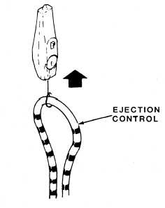
Ejection Control Assembly Check-out
Checking the ejection control assembly is a
four part procedure. The first part of the
procedures shown in figure 6-47.
1. Install the initiation pull-test tool set.
Ensure the ejection initiator pull-test tools are not
preloaded. Position the safe/arm control to the
full UP position. Attach a push-pull gauge to the
ejection control assembly. Pull upward and record
the breakout force. The breakout force should be
15 to 25 pounds.
2. Lower the safe/arm control to the full
DOWN position. Continue pulling upward on the
ejection control assembly until the pull-test tools
extend to the relaxed position. The force required
to accomplish this task should be 15 to 40 pounds.
You should ensure that the ejection control
assembly does not separate from the seat. You
should also observe the initiation rotors rotating
past the safety plunger.
3. Stow the ejection control assembly while
manually returning the initiation subsystem
rotors to the ARMED position. Then install the
initiation pull-test tool to the upper connect and
disconnect sear. At this point you can simulate
automatic seat/man separation by rotating the
emergency release handle to the full UP position.
Notice that the upper connect and disconnect sear
moves down, and the pull-test tool extends to the
relaxed position. Check to see that the T-bar is
Figure 6-47.—Ejection control assembly check-out.
in the full UP position, and that it is blocking the
initiation rotors.
4. Raise the safe/arm control to the UP and
LOCKED position. Lower the emergency release
handle to the DOWN and LOCKED position.
Remove the initiation pull-test tool set.
Inertia Reel Assembly Check-out
The inertia reel check-out may be grouped into
seven steps. The test is shown in figure 6-48.
1. Insert the bridle rod through both the
parachute riser loops. Position the inertia reel
manual control to UNLOCK. Then grasp the
center of the bridle rod and extend the risers to
mid position. Hold the risers extended and
position the inertia reel manual control lever to
LOCK. When you pull firmly on the center of the
bridle rod, the risers should not extend.
2. Slowly allow the risers to retract. The risers
retracting and ratcheting action should be audible
during retraction. The inertia reel control lever
should not snap into position, or the test results
will not be valid.
3. Slowly position the inertia reel manual
control lever to UNLOCK. Grasp the center of
the bridle rod and extend both risers to the mid
position. Exert a sharp pull on the bridle rod. The
inertia reel should lock and the risers should not
extend when a firm pull is applied. Slowly allow
the risers to fully retract, and then pull the risers
again. You should not be able to extend the risers.
4. Position the lever to LOCK, and then
UNLOCK and extend and retract the risers. The
risers should extend and retract freely.
5. Attach a push-pull gauge to the bridle rod.
Pull the gauge straight and extend the risers. You
should record the force required to extend them.
Repeat the step three to five times. The risers
should extend with a force of 5 to 15 pounds.
Allow the riser to retract slowly.
6. Position a 24-inch steel rule against the for-
ward edge of the yoke and perpendicular to the
catapult tubes. Without extending the inertia reel
straps, lift the bridle rod and measure the
normal extension of the risers. You should record
this measurement. Pull on the bridle rod and
measure the full extension of the risers. Again,
record the measurement. Allow the risers to
retract slowly. At full extension, you should
observe a minimum of 18 inches. Then, subtract
the normal measurement from the extended
measurement. The difference between the
5-66