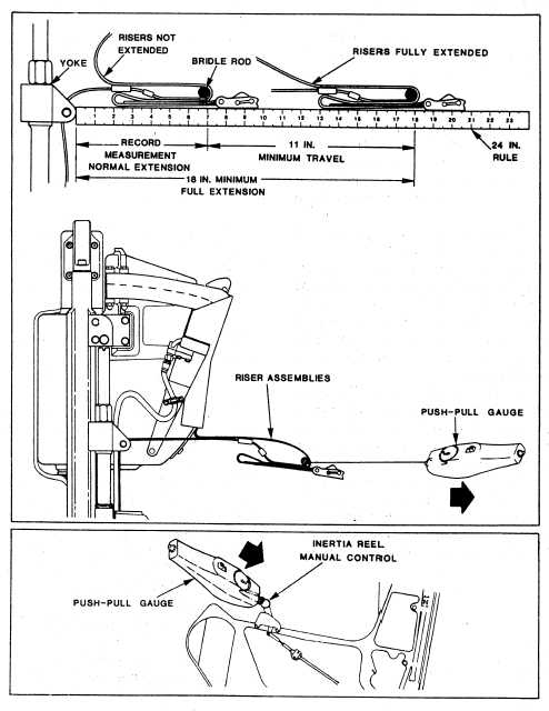
Figure 6-48.—Inertia reel assembly check-out.
measurements should be a minimum of 11 inches
with a maximum of 25 pounds of force. Allow
of total riser travel.
the risers to completely retract and remove the
spring scale and bridle rod.
7. Position the inertia reel control to LOCK.
Attach a spring scale to the center of the bridle
rod. Position a push-pull gauge against the for-
Seat Height Adjustment
ward edge of the control knob parallel to the seat
Actuator Check-out
side panel. Apply a 50-pound pull to the bridle
rod and maintain this tension while applying a
Removal of the wedge and survival kit
push force to the control knob. The control knob
assemblies is. not required to complete the
should move, without binding, to the aft position
five steps of the seat’ height adjustment actuator
6-67

