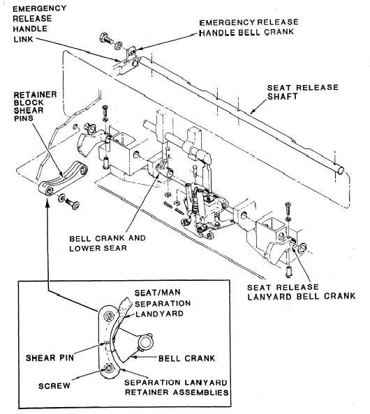
7. Lower the safe/arm control to the DOWN
and LOCKED position. Simulate a seat/man
separation by unlocking the emergency release
handle. Pull upon both the seat and man separa-
tion lanyards. Observe that the seat release shaft
rotates to the released position and the seat/man
separation upper sear moves downward. You
should also notice that the seat/man separation
lanyards release from the bell cranks.
8. Attach the seat release lanyards to the seat
release lanyard bell cranks. At this point, make
sure that the seat release lanyards are not pinched
between the seat release lanyard bell cranks and
the slots in the lanyard retainer assemblies. Rotate
the seat release lanyard bell cranks down below
the shear pins in the lanyard retainer assemblies.
You should ensure that the lanyards remain
attached to the bell cranks. Rotate the lanyard
retainer assemblies up and aft and install the top
screws and washers. Tighten the bottom screws
in the lanyard assemblies. When you apply light
hand pressure, you should observe freedom of
movement in the bell cranks.
9. Lower the emergency release handle to the
DOWN and LOCKED position. Remove the
initiation pull-test tool set.
Figure 6-46.—Separation lanyard retainer assemblies.
6-65


