RECEIVER.-
The receiver acts as a reservoir
for the liquid Freon 12 refrigerant. The fluid level
in the receiver varies with
system demands.
During peak cooling periods, there will be less
liquid than when the load is light. The purpose
of the receiver is to ensure that the thermostatic
expansion valve is not starved for refrigerant
under heavy cooling load conditions.
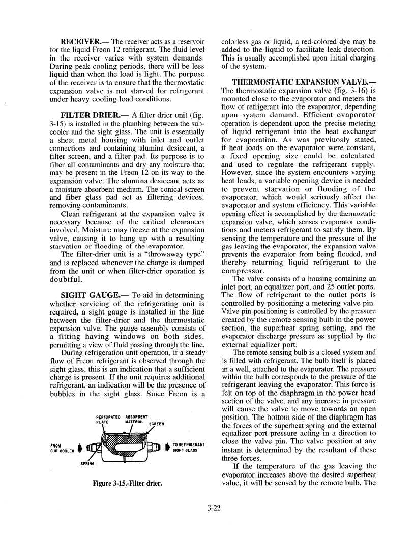
FILTER
DRIER.-
A filter drier unit (fig.
3-15) is installed in the plumbing between the sub-
cooler and the sight glass. The unit is essentially
a sheet metal housing with
inlet and outlet
connections and containing alumina desiccant, a
filter screen, and a filter pad. Its purpose is to
filter all contaminants and dry any moisture that
may be present in the Freon 12 on its way to the
expansion valve. The alumina desiccant acts as
a moisture absorbent medium. The conical screen
and fiber glass pad act as filtering
devices,
removing contaminants.
Clean refrigerant at the expansion valve is
necessary because of the critical
clearances
involved. Moisture may freeze at the expansion
valve, causing it to hang up with a resulting
starvation or flooding
of the evaporator.
The filter-drier
unit is a “throwaway
type”
and is replaced whenever the charge is dumped
from the unit or when filter-drier
operation is
doubtful.
SIGHT
GAUGE.-
To aid in determining
whether servicing of the refrigerating
unit is
required, a sight gauge is installed in the line
between the filter-drier
and the thermostatic
expansion valve. The gauge assembly consists of
a fitting
having
windows
on both
sides,
permitting a view of fluid passing through the line.
During refrigeration unit operation, if a steady
flow of Freon refrigerant is observed through the
sight glass, this is an indication that a sufficient
charge is present. If the unit requires additional
refrigerant, an indication will be the presence of
bubbles in the sight glass. Since Freon is a
PERFORATED
ABSORBENT
PLATE
.
MA:ER’AL
SCREEN
FROM
a
TO REFRIOERANT
SUB-COOLER
SiGilT
GLASS
Figure 3-E-Filter drier.
colorless gas or liquid, a red-colored dye may be
added to the liquid to facilitate leak detection.
This is usually accomplished upon initial charging
of the system.
THERMOSTATIC
EXPANSION
VALVE.-
The thermostatic expansion valve (fig. 3-16) is
mounted close to the evaporator and meters the
flow of refrigerant into the evaporator, depending
upon system demand. Efficient
evaporator
operation is dependent upon the precise metering
of liquid
refrigerant
into the heat exchanger
for evaporation.
As was previuosly
stated,
if heat loads on the evaporator were constant,
a fixed
opening
size could
be calculated
and used to regulate the refrigerant
supply.
However, since the system encounters varying
heat loads, a variable opening device is needed
to prevent
starvation
or flooding
of the
evaporator, which
would
seriously affect the
evaporator and system efficiency. This variable
opening effect is accomplished by the thermostatic
expansion valve, which senses evaporator condi-
tions and meters refrigerant to satisfy them. By
sensing the temperature and the pressure of the
gas leaving the evaporator, the expansion valve
prevents the evaporator from being flooded, and
thereby
returning
liquid
refrigerant
to the
compressor.
The valve consists of a housing containing an
inlet port, an equalizer port, and 25 outlet ports.
The flow of refrigerant
to the outlet ports is
controlled by positioning a metering valve pin.
Valve pin positioning is controlled by the pressure
created by the remote sensing bulb in the power
section, the superheat spring setting, and the
evaporator discharge pressure as supplied by the
external equalizer port.
The remote sensing bulb is a closed system and
is filled with refrigerant. The bulb itself is placed
in a well, attached to the evaporator. The pressure
within the bulb corresponds to the pressure of the
refrigerant leaving the evaporator. This force is
felt on top of the diaphragm in the power head
section of the valve, and any increase in pressure
will cause the valve to move towards an open
position. The bottom side of the diaphragm has
the forces of the superheat spring and the external
equalizer port pressure acting in a direction to
close the valve pin. The valve position at any
instant is determined by the resultant of these
three forces.
If the temperature of the gas leaving the
evaporator increases above the desired superheat
value, it will be sensed by the remote bulb. The
3-22