indication of flow and proper refrigerant charge.
The refrigerant is metered by the thermostatic
expansion valve, and then enters the evaporator
assembly. The hydraulic motor-driven evaporator
fan forces warm electronic equipment compart-
ment air through the evaporator assembly, where
it is cooled by transfer of heat to the refrigerant.
The refrigerant leaves the evaporator as a
superheated vapor.
The temperature of evaporator discharge air
to the equipment compartment is controlled by
controlling the speed of the compressor motor.
The evaporator pressure control system maintains
the refrigerant pressure within a specified range
so that the average temperature range of the
refrigerant is between 29.8° and 32.9° ± 0.6°F.
This temperature range consequently controls air
temperature to approximately 38°. The difference
between the air and refrigerant temperatures is due
to the efficiency of the heat exchanger.
If the equipment compartment temperature
increases, refrigerant pressure on the low side will
also increase. The increase in pressure is sensed
by a pressure transducer located in the compressor
inlet line, and a signal is sent to the evaporator
pressure control system amplifier. The amplifier,
in turn, sends an appropriate signal to the servo
portion of the compressor hydraulic motor calling
for a speed increase to prevent pressure increase
and thus maintain a constant refrigerant pressure.
If the temperature increase calls for a compressor
motor speed above a maximum of 12,000 rpm,
the temperature rise cannot be compensated for
and the refrigerant pressure will rise. At 250 ± 5
psi compressor discharge pressure, the high side
cutout switch will shut the vapor cycle system
down.
If the equipment compartment temperature
drops, a reverse situation exists. Compressor
motor speed will decrease to a minimum of 4,000
rpm. If the temperature at the fan inlet continues
to drop beyond the range that can be compensated
(30°F), the low-temperature cutoff switch
de-energizes the compressor power relay and shuts
down the compressor motor. The refrigerant stops
flowing while the evaporator fan motor continues
to circulate compartment air. When the fan inlet
temperature rises to 40° ± 2°F, the compressor is
cut in and refrigerant flows through the
evaporator and the subcooler and returns to the
compressor to repeat the cycle.
The purpose of each major component in the
vapor cycle system is discussed in the following
paragraphs.
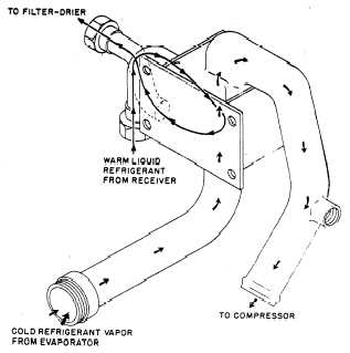
SUBCOOLER.— The subcooler (fig. 3-14) is
a heat exchanger containing passages for liquid
Freon 12 from the receiver on its way to the
evaporator and cold Freon gas leaving the
evaporator on its way to the compressor.
The purpose of the subcooler is to increase the
efficiency of the system by cooling the refrigerant
after it leaves the receiver, thereby preventing
premature vaporization or flash off after passage
through the expansion valve and before it reaches
the evaporator. As stated previously, the refrigera-
tion effect takes place when the Freon changes
state from liquid to gas. Premature flash off
would result in keeping additional refrigerant
from evaporating and would have no useful
effect on the primary cooling load required of the
package.
The liquid on the way to the thermostatic
expansion valve is relatively warm in comparison
to the cold gas leaving the evaporator. Although
the gas leaving the evaporator has absorbed heat
from the air being circulated through the
evaporator, its temperature is still in the vicinity
of 40°F. This cool gas is fed through the subcooler
where it picks up additional heat from the
relatively warm liquid Freon 12 that is flowing
from the receiver. This heat exchange causes the
liquid to be subcooled to a level that ensures
little or no flash gas on its way to the evaporator.
Figure 3-14.—Subcooler.
3-21