All machinery control system (MCS) consoles,
except the bridge control unit (BCU), are protected from
a loss of 155-volt dc electrical power. The UPS battery
cells located in each console provide this protection. The
c a p a c i t y of the multicell battery pack powers its
connected units for at least 30 minutes following a
power failure. The batteries are contained in fumetight,
slide-mounted assemblies that are vented outside the
MCS consoles. Each console has from one to three racks
of cells, depending on its power requirements. The
b a t t e r y - c h a r g i n g circuits of each console can
a u t o m a t i c a l l y recharge a battery from 40 percent
capacity to 80 percent capacity within 8 hours. Battery
charging does not affect normal MCS operation.
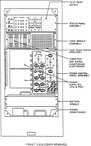
The interim integrated electronic control (IIEC)
also includes an UPS battery pack system. The IIEC
contains the electronic support module (ESM) and the
engine control module (ECM). (See fig. 2-4) The IIEC
performs functions similar to those of the free standing
electronics enclosure (FSEE) on other gas turbine ships.
The battery pack for the IIEC is contained in the ESM.
The ECM also uses the UPS battery pack that is
contained in the ESM.
T h e MCS consoles require single-phase and
3-phase, 115-volt ac, 60-Hz power. The single-phase
power energizes the console heating elements whenever
the 3-phase power is not in use. The normal power
source for each MCS console is the 3-phase, 115-volt
ac. Its use raises console temperatures above expected
Figure 2-4.--Electronic support module (ESM).
dew point levels, avoiding hardware problems. The
heating elements maintain the protected environment
when the consoles are off-line.
charger assembly logic is designed to use the normal
The MCS console battery charger will
power source when it is available.
automatically shift the load to battery power when the
normal power supply fails. The batteries, located in the
lower section of the console, are a 155-volt dc source.
BATTERY MAINTENANCE
When the shift to UPS power occurs, an alarm will
sound and the UPS IN USE indicator on the console will
You must give the same careful attention to the
illuminate. A message showing that a particular console
maintenance of UPS batteries that you would to the
is on UPS will be displayed on the plasma display units.
maintenance of any other power unit. Lack of intelligent
The UPS is designed to supply needed power for a
supervision in the care of a UPS battery can result in
minimum of 30 minutes.
temporary impairment or permanent damage. Carefully
Normal or UPS battery power enters the console
follow all instructions contained in the maintenance
power distribution system through the power control
requirement cards (MRCs), manufacturer's technical
panel assembly. Three-phase voltage is rectified to +155
manual, and data on the battery nameplates. These
volts dc in the power conditioner and sent to the battery
instructions will help you make sure the batteries
charger. This normal 155-volt dc power automatically
perform as designed. In the following paragraphs, we
charges the UPS batteries and provides input to the
will briefly discuss some of the maintenance tasks and
power supplies. The UPS battery power is connected to
procedures you will use with the UPS battery systems.
the power supplies when the load shifts. The battery
2-4

