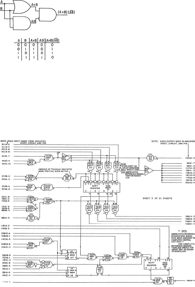
Detailed logic diagrams show all logic functions of
the equipment concerned. In addition, they also include
such information as socket locations, pin numbers, and
test points to ease troubleshooting. A detailed logic
diagram for a complete unit may consist of many
separate sheets. An example of a detailed logic diagram
is shown in figure 1-22.
EQUIPMENT LAYOUTS
Engineering personnel use equipment layouts as
aids to locate various pieces of equipment throughout a
Figure 1-21.--Basic logic diagram.
machinery space. Equipment layouts are extremely
helpful to newly reporting personnel who are not
familiar with the engineering spaces. The main purpose
of logic diagrams. There are two types of logic
o f an equipment layout is to show the physical
diagrams-basic and detailed.
relationship of the equipment to its location in a space.
Basic logic diagrams show a particular operating
Some layouts are more detailed than others, but the
unit or component. Figure 1-21 is an example of a basic
primary purpose is the same. While some equipment
logic diagram. In a basic logic diagram, basic logic
l a y o u t s may show only the physical location of
machinery, others will show the piping that connects
symbols are shown in their proper relationship to show
various pieces of equipment together.
operation only in the most simplified form.
Figure 1-22.--Detailed logic diagram.
1-24

