Isometric Wiring Diagram
An isometric wiring diagram shows the outlines of
a ship and the location of equipment, such as panels,
connection boxes, and cable runs.
Wiring Diagram
A wiring diagram shows the individual connections
within a unit and the physical arrangement of the
components.
Schematic Diagram
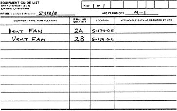
Figure 1-20.--Standard Equipment Guide List.
A schematic diagram uses graphic symbols to show
how a circuit functions electrically.
Remember, each page of an EGL should contain no
Elementary Wiring Diagram
more than a single day's work. If more than one day is
required, prepare a separate EGL page for each day, and
An elementary wiring diagram shows how each
number the pages consecutively.
conductor is connected within the various connection
boxes of an electrical circuit or system.
DIAGRAMS AND EQUIPMENT
LAYOUTS
Block Diagram
Drawings and equipment layouts are the universal
A block diagram includes the major components of
language used by engineers and technicians. They
an equipment item or system by means of squares,
convey all the necessary information to the individual
rectangles, or other geometric figures.
who will maintain, operate, and repair the equipment
and machinery.
Single-Line Diagram
To complete assigned tasks, a GSE must be able to
read and understand electrical and electronic prints and
A single-line diagram uses lines and graphic
diagrams. To read any electrical or electronic print, you
symbols to simplify a complex circuit or system.
must be familiar with the standard symbols used for
t h e s e prints and the various methods of marking
ELECTRONIC PRINTS
electrical conductors, cables, and equipment items.
Most of the work performed by GSEs involves the
ELECTRICAL PRINTS
maintenance and upkeep of the Engineering Control and
Surveillance System (ECSS) consoles. A different type
o f diagram is used to troubleshoot the complex
GSEs use Navy electrical prints in the installation,
components of these consoles. For this reason, a GSE
m a i n t e n a n c e , and repair of shipboard electrical
will use electronic prints more often than electrical
equipment and systems. These prints include various
prints. Electronic prints are similar to the electrical
types of electrical diagrams. The following sections will
prints discussed earlier. Electronic prints, however, are
provide a brief description of these prints. For more
usually more difficult to read than electrical prints
detailed information, refer to Blueprint Reading and
because they represent more complex circuitry and
Sketching, NAVEDTRA 10077-F1.
systems. Shipboard electronic prints include isometric
wiring diagrams, block diagrams, schematic diagrams,
Pictorial Wiring Diagram
and interconnection diagrams.
A pictorial wiring diagram shows actual pictorial
Associated with some electronic prints are logic
sketches of the various parts of an equipment item and
d i a g r a m s . Operation and maintenance of digital
the electrical connections between the parts.
computers and digital computer systems requires the use
1-23

