When it is in the ON position, the ON-OFF switch
energized from the ship's 120-volt ac, 3-phase, 60-Hz
power source.
connects 120 volts dc to the oscillator. The 120 volts dc
T h e battery charger/rectifier is connected to
must be applied to the oscillator before the 120 volts dc
maintain the charge of the ship's battery bank while
is energized to the inverter. The 120 volts dc must
simultaneously supplying power to the inverter. Upon
remain on until after the inverter is de-energized to avoid
failure of the ship's ac input to the UPS, power from the
possible damage to the parts of the inverter.
ship's battery bank will automatically provide dc power
The ship's UPS battery bank is connected to the
to drive the inverter. This causes the inverter to maintain
battery charger/rectifier by a circuit breaker. The output
the ac output to the load without power interruption for
from the battery charger/rectifier maintains the charge
up to 15 minutes. When the ship's ac input returns, the
on the batteries during regular conditions. The batteries
battery charger/rectifier of the UPS will supply the
may be discharged while they are supplying 120 volts
inverter and charge the battery bank. The transfer of
dc to the inverter if the ships's service power to the UPS
power to and from the battery bank takes place without
is de-energized. When ship's service power returns to
any interruption of power.
the UPS, it allows the battery charger/rectifier to
The ship's service 120 volts ac is supplied through
recharge the battery bank to full charge.
a circuit breaker to a transformer and then rectified to
The UPS system is equipped with instrument and
produce the 120 volts dc. The 120 volts de is applied to
indicator light monitoring devices. These devices
an oscillator and a single-phase bridge inverter. The
120-volt ac, 60-Hz, 1-phase output of the inverter is the
p r o v i d e a continuous visual display of the UPS
normal input to the automatic load transfer switch. To
operation. They consist of power available indicators, a
supply power if the inverter fails, one phase of the ship's
120-volt ac, 3-phase power supply is routed to the
oscillator-inverter status indicator lights. The system
alternate input to the automatic load transfer switch.
also contains four devices that show the UPS output
T h e control devices of the UPS consist of a
power condition and three indicator lights that show
four-position mode switch and a two-position ON-OFF
which power source is supplying the load.
switch. The mode switch selects NORMAL,
ALTERNATE, AUTOMATIC, or OFF. NORMAL
selects inverter output only and ALTERNATE selects
DDG-51 CLASS SHIPS
ship supply output only. AUTOMATIC selects the
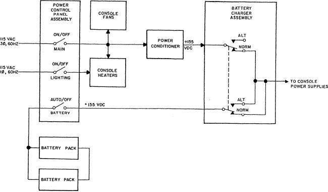
Figure 2-3 shows a block diagram of the UPS
transfer switch selected output and OFF removes UPS
from the output circuit breaker.
system used on DDG-51 class ships.
Figure 2-3.--Block diagram of the UPS system for DDG-51 class ships.
2-3

