PACKING AND
Piping should be tested at the frequency and
GASKET MATERIAL
test pressure specified following the PMS and the
applicable equipment technical manual. Test
Packing and gasket materials are required to
pressure must be maintained long enough to show
seal joints in steam, water, gas, air, oil, and other
any leaks or other defects in the system.
lines and to seal connections that slide or rotate
Instruction manuals should be available and
under normal operating conditions. There are
followed for the inspection and maintenance of
many types and forms of packing and gasket
piping systems and associated equipment;
materials available commercially.
however, if the manufacturer's instruction manual
is not available, you should refer to Naval Ships'
PACKING AND GASKET SELECTION
Technical Manual, chapter 505, for details of
To simplify the selection of packing and gasket
piping inspection and maintenance.
materials commonly used in naval service, the
Naval Sea Systems Command has prepared a
PIPING SYSTEM
packing and gasket chart, Mechanical Standard
IDENTIFICATION MARKING
Drawing B-153 (see fig. 6-47 at the end of
this chapter). It shows the symbol numbers and
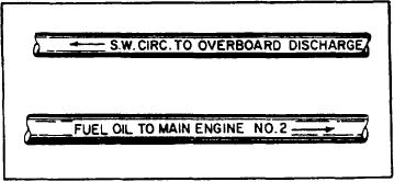
All piping should be marked to show the name
the recommended applications for all types and
of the service, destination (where possible), and
kinds of packing and gasket materials.
direction of flow (fig. 6-46).
The symbol number used to identify each type
The name of the service and destination should
of packing and gasket has a four-digit number.
be painted on by stencil or hand lettering, or by
(See List of Materials in fig. 6-47.) The first digit
application of previously printed, stenciled, or
shows the class of service with respect to fixed and
lettered adhesive-backed tape. Lettering will be
moving joints; the numeral 1 shows a moving joint
1 inch high for a 2-inch or larger outside diameter
(moving rods, shafts, valve stems), and the
bare pipe or insulation, For smaller sizes,
numeral 2 shows a fixed joint (flanges, bonnets).
lettering size may be reduced or label plates
The second digit shows the material of which the
attached by wire or other suitable means.
packing or gasket is primarily composed--
Direction of flow will be indicated by an
asbestos, vegetable fibre, rubber, metal, and so
arrow 3 inches long pointing away from the
forth. The third and fourth digits show the
lettering. For reversible flow, arrows are to be
different styles or forms of the packing or gasket
shown on each end of the lettering.
made from the material.
Black is used for lettering and arrows.
Practically all shipboard packing and gasket
However, on dark-colored pipe (including oxygen
problems can be solved by selection of the
piping), white is used.
correct material from the listings on the packing
Markings will be applied to piping in
and gasket chart. The following examples show
conspicuous locations, preferably near the
control valves and at suitable intervals so every
the kind of information that you can get from the
packing and gasket chart.
line will have at least one identification marking
Suppose you are required to repack and
in each compartment through which it passes.
install a valve in a 150-psi seawater service system.
Piping in cabins and officers' wardrooms will not
Refer to figure 6-47, the packing and gasket chart.
normally be marked.
Under the subhead Symbols and Specifications
for Equipments, Piping and Independent Systems,
you find that symbol 1103 indicates a suitable
material for repacking the valve. Notice that the
first digit is numeral 1, indicating that the material
is for use in a moving joint. Under the List of
Materials, you find the packing is asbestos rod,
braided.
For installing the valve, you need proper
gaskets. By use of the same subhead, you find that
symbols 2150, 215l type II, 2152, and 2290 type
II are all suitable for installing the valve. Notice
that the first digit is numeral 2, which indicates
that it is designed for fixed joints. Again, by
Figure 6-46.--Pipe markings.
6-33

