
both the FSCC and the JP-5 local control panel
panels to operate indicators energized by the local
meters function.
panels.
FUEL OIL TRANSFER LOCAL PANELS
Associated with the FSCC are two FO transfer
The FSCC has eight dc power supplies located
local panels. (See fig. 9-13.) Panel No. 1, located
in the power supply drawers 1A3A3, 1A2A3, and
in auxiliary machinery room (AMR) No. 1,
1A1A3 (+5 V, -5 V, +12 V, and +24 V). Two
monitors and controls the No. 1 FO transfer
supplies are used for each voltage level. They
pump, heater, purifier, and associated valves.
normally operate in parallel, sharing the current
Panel No. 2, located in AMR No. 2, monitors and
load. The LEDs at the power supplies show
controls the No. 2 FO transfer equipment.
voltage output. If one supply of a pair should fail,
Controls and indicators are similar to those on
the LED for that supply extinguishes and the other
the FSCC but pertain only to the equipment
power supply of the pair will automatically supply
associated with the particular local panel.
the load. Isolation diodes between the power
Information is exchanged between each of the
supplies prevent the failed supply from absorbing
local panels and the FSCC.
current. Each power supply has an output voltage
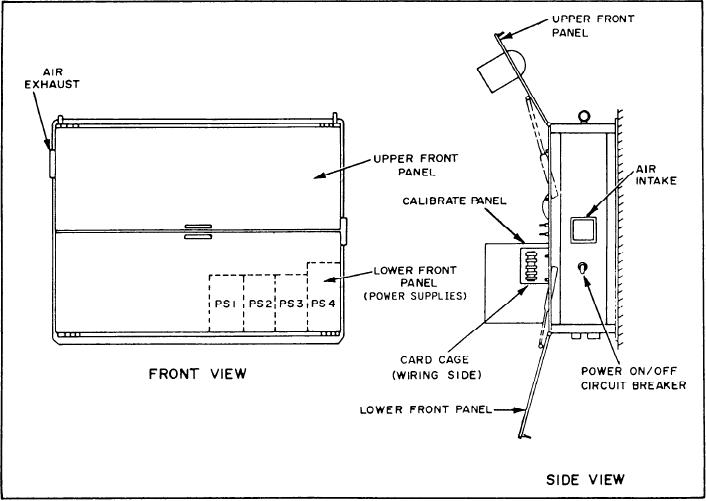
The FO transfer local panels are bulkhead
adjust potentiometer (R1) that serves to calibrate
mounted. They have an upper and lower front
the supply within its specified tolerance.
panel and a metal enclosure that houses the power
The FSCC sends +24 volt dc power to all three
supplies and electronic circuits. The upper and
local panels for illumination of indicators
lower front panels swing open for maintenance
controlled by the FSCC. The FSCC also receives
and card cage access. Figure 9-14 is an outline of
+24 volt dc power from the three local control
the FO transfer local control panel.
Figure 9-14.--Fuel oil and JP-5 local control panels--component location.
9-17