Power Application
Power Distribution Panel
The JP-5 local control panel has a power
The FSCC is energized from the fuse and CB
panel. The three power supply panel switches
distribution panel. It is similar to those in the FO
(S1, S2, and S3) should be in the ON position.
local control panels.
Placing the main power CB (CB1) in the ON
position then energizes the FSCC. All power
Calibrate Panel
supply indicator lights should be on. Since
application of power to the console may alarm
The calibrate panel of the JP-5 local control
some circuits, all flashing push-button indicators
panel is similar in function to those in the FSCC
and FO local control panels. The only circuits
should be depressed to reset the alarm circuitry.
serviced by this panel are the JP-5 service tank
To energize the JP-5 local control panel and
the FO local control panels, place the ac power
level high and low alarm functions. No mode
CBs in the ON position. To reset any alarms,
switches are on this panel. This is because the only
depress any flashing push-button indicators.
JP-5 service tank level meters are at the JP-5 local
control panel.
Self-Tests
OPERATION
The FSCC and the three local panels are
equipped with alarm and lamp tests. Depressing
This section is limited to general procedures
the HAZARD ALARM TEST push button causes
for the FSCC and local panel power application,
each hazard alarm circuit in the associated panel
self-test, FO fill control, and turnoff. You can
find detailed instructions for starting, operating,
to activate (4-Hz flashing indicator and 4-Hz
and securing this equipment in the Fuel Control
tone). You must acknowledge each hazard alarm.
This test also starts associated remote hazard
System Consoles technical manual.
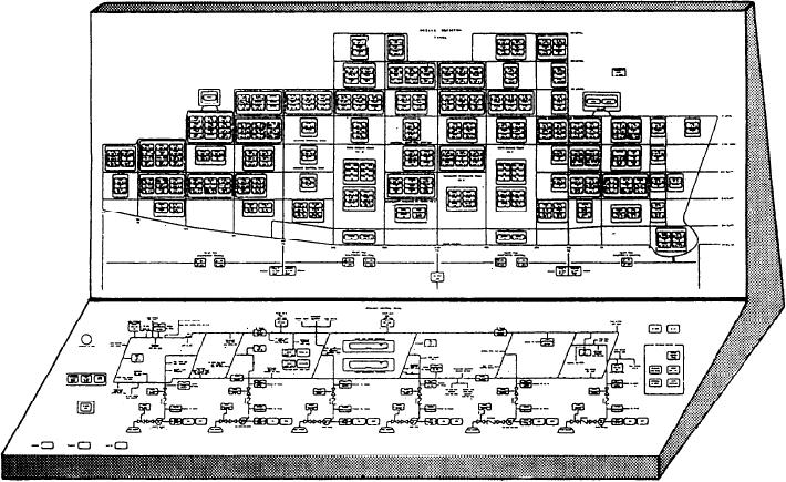
Figure 9-17.--Damage control console (DD-963 class).
9-20

