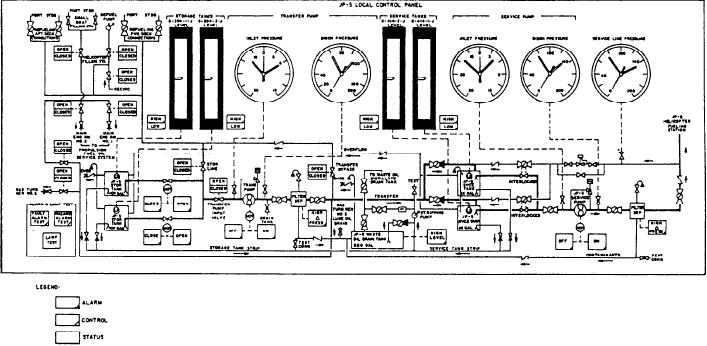
Figure 9-16.--JP-5 local control panel.
FSCC calibration panel serves the FSCC circuits.
service operations because the FSCC has
At this panel, you can calibrate the associated
provisions only for limited monitoring and
service tank level, transfer pump pressure, FO
terminating of these operations.
heater temperature, and purifier pressure meter
circuits. You can also set the alarm points for
All pressure monitoring at the JP-5 local
service tank level (HI/LO), transfer pump
control panel is done with pressure gauges. At the
pressure, and purifier discharge pressure at this
top of the enclosure are gauge cutout valves for
panel. All seven meter circuits have mode
each of the gauges. Because the alarms, indicators,
switches for selection of LOCAL AND REMOTE
and push buttons are identical to those on the
or LOCAL ONLY displays.
FSCC JP-5 control panel, we will not discuss these
components.
JP-5 LOCAL CONTROL PANEL
Primary control of the JP-5 fill system is
accomplished from the FSCC in CCS. Transfer
and service system control is accomplished from
The JP-5 local control panel has four power
the JP-5 local control panel located in pump room
supplies, one for each dc voltage level used (+5 V,
No. 2. The JP-5 local control panel is similar in
5 V, +12 V, and +24 V). The arrangement of
construction to the FO local control panel shown
these power supplies in the enclosure is similar to
in figure 9-16. The monitoring and control
that in the FO local control panel. Twenty-four
functions of this panel are for the JP-5
volts is sent to the FSCC for illumination of
fill, transfer, and service systems. This panel
indicators controlled by the local panel. All four
exchanges information with the FSCC only.
power supplies are energized by the CB1.
Operator's Panel
Card Cage
The upper front panel of the JP-5 local
control panel has the meters, gauges, indicators,
The card cage, mounted on a hinged panel
and push buttons necessary to operate the JP-5
common with the calibrate panel, houses the 12
PCBs that control and monitor the functions of
fill, transfer, and service systems. This panel is
the primary control center for JP-5 transfer and
the local panel.
9-19

