
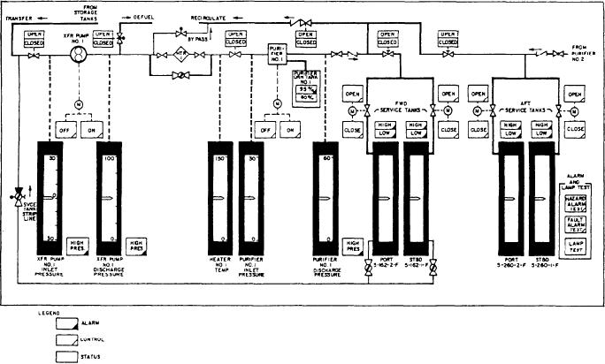
Figure 9-15.--Fuel oil transfer local panel No. 1.
The meters, indicators and controls on the
power output is less. Each power supply voltage
local FO transfer panel are identical to those on
is adjustable. Each local panel sends 24-volts dc
the FSCC. Since the FO transfer local panels and
power to the FSCC. This is used to illuminate
the FSCC contain identical components, we will
remote indicators controlled by the local panel.
not discuss the FO transfer local panels. Figure
9-15, however, shows a detailed view of one of
Card Cage
the local panels.
Normally there is little maintenance necessary
The card cage, mounted on a hinged panel
for the FO transfer local panels besides changing
with the calibrate panel, houses the 13 PCBs for
light bulbs. However, there are circumstances that
each FO local control panel. These cards monitor
arise when the panels are required to be tested and
and control the functions of the local panel.
calibrated. To perform these test and calibration
Power Distribution Panel
procedures, the operator must be familiar with
the internal components of the FO transfer local
Each FO local control panel assembly houses
panels. We will discuss these components in the
following paragraphs. Refer to figure 9-14 while
a power distribution panel (not shown). This panel
you read this discussion.
has the terminal boards for panel connections and
the protective fuses for that particular panel.
Power to a local panel is controlled by one ac
CB, CB1. This CB is located on the right side of
Each FO local control panel has four power
the enclosure. (See fig. 9-14.)
supplies, one for each dc voltage level used
(+5 V, 5 V, +12 V, and +24 V). The local +5
Calibrate Panel
volt, 5 volt, and + 12 volt supplies are the same
Each FO local control panel has a calibrate
type as those in the FSCC. The 24-volt supply used
in the local panels is functionally similar to the
panel. It serves the monitor and alarm circuits of
the local panel in the same manner in which the
FSCC 24-volt supply; however, the maximum
9-18