
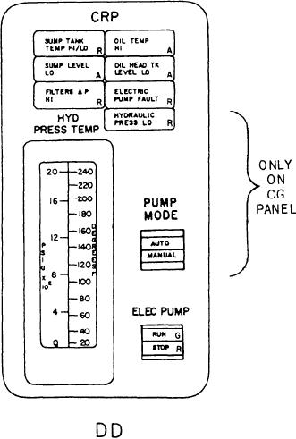
The push-button control indicator on the
point. To the right is an alarm indicator labeled
DD console under the label ELEC PUMP has a
OIL TEMP HI. It is an amber indicator that
split-legend indicator labeled RUN/STOP. It is
illuminates when the temperature of the LO from
used to control the CRP electric LO pump and
the pump to the system exceeds its alarm set point.
illuminates (either green or red) to indicate the
The next alarm indicator is labeled SUMP LEVEL
status and operator command to the pump.
LO. It is also an amber indicator that illuminates
when the CRP sump tank LO level is below 500
gallons. To the right is an alarm indicator
labeled OIL HEAD TK LEVEL LO. It is an
amber indicator that illuminates when the CRP
head tank LO level is below 10 gallons. On the
third row is the alarm indicator labeled FILTERS
Ć P HI. It is a red indicator that illuminates when
the LO pressure across either of the three filters
on the hydraulic oil power module (HOPM) of
the CRP system exceeds its alarm set point. The
last alarm indicator on the DD console is labeled
ELECTRIC PUMP FAULT. It is a red indicator
that illuminates when the electric pump is
running and pump discharge pressure drops below
100 psig for more than 5 seconds.
On the CG console, the last alarm indicator
is labeled HYDRAULIC PRESS LO. It illuminates
red when the pump discharge pressure drops
below 100 psig for 5 seconds.
The only meter associated with the CRP is
labeled HYD PRESS TEMP. It is a dual-
indicating meter used to monitor the pressure and
temperature of the HP oil at the output of the
HOPM to the OD box.
The push-button control indicator on the CG
console under the label PUMP MODE has a split-
legend indicator, labeled AUTO/MANUAL. If
the AUTO mode is selected by the PACC
operator, the electric CRP pump will come on the
FUEL OIL Section
line if any one of the following conditions are true:
This section is used to monitor the FO service
1. The attached pump output pressure is
system. It has 11 alarm indicators, 10 status
< 100 psig for 1 second.
indicators, a meter, 4 valve control switches, a
2. Shaft speed is < 90 rpm for 10 seconds.
three-position rotary switch for pump mode
3. If the pitch mismatch > 10 percent for 1
control, 6 push-button control indicators, and
second.
2 station-in-control status indicators.
NOTE
The first two alarm indicators are a pair of
functionally identical indicators. They are labeled
On the CG-class ship, if the electric
PUMP B FAULT and PUMP A FAULT. These
pump control mode is in auto, once the
indicators are red and illuminate when either FO
hydraulic oil pressure recovers (as a result
service pump is running and the pump discharge
of pump speed increase or other operator
pressure drops below 35 psig for 5 seconds. The
actions) the electric pump must be manually
next alarm indicator is labeled FILTER Ć P HI.
secured by the PACC operator.
5-4