
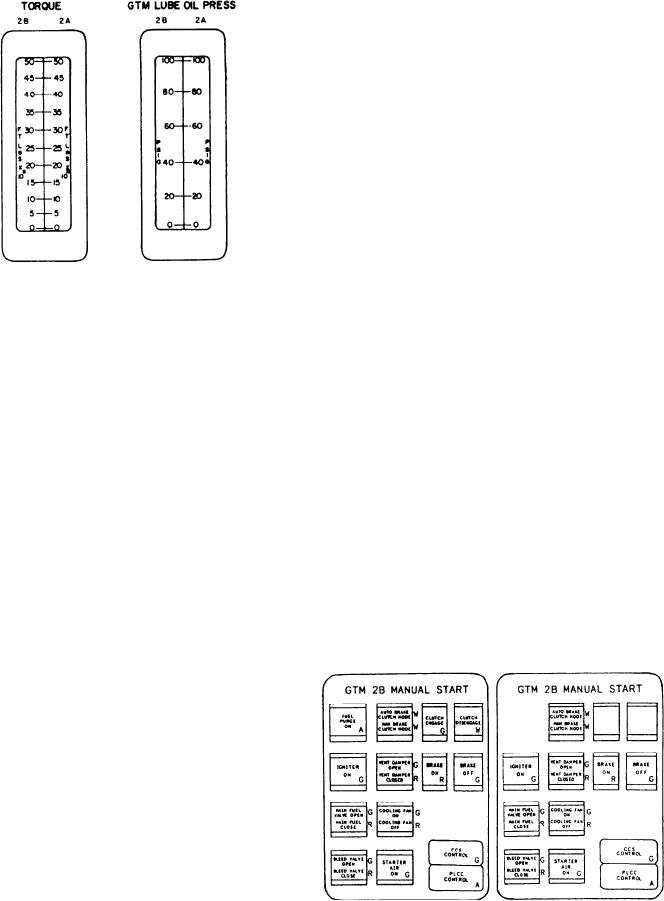
(illuminates red to show command), and BRAKE
supply pump and are sent to the console for
OFF (illuminates green to show command).
display.
The push-button control indicator on the
second row labeled IGNITER ON illuminates
green when the PACC operator commands the
igniters on during a manual start. It also
illuminates when the igniters are energized during
an auto initiate start. The next split-legend,
push-button control indicator is labeled VENT
DAMPER OPEN/VENT DAMPER CLOSED.
It illuminates to show the command to the vent
damper. On the third row is a split-legend, push-
button control indicator labeled MAIN FUEL
VALVE OPEN/MAIN FUEL VALVE CLOSED.
It illuminates to show the command to the fuel
supply valve during a manual start, auto start,
manual stop, or auto stop. The split-legend, push-
button control indicator labeled COOLING FAN
ON/COOLING FAN OFF illuminates to show
the PACC operator's command to the cooling fan
during a manual start. It also illuminates when the
In the subsection labeled GTM 2B MANUAL
electronics generates the command during an auto
START are 12 push-button control indicators (9
start. On the fourth row is a split-legend, push-
on the CG console) and 2 status indicators. The
button control indicator labeled BLEED VALVE
first push-button control indicator (not on the
OPEN/BLEED VALVE CLOSE. It illuminates
CG console) is labeled FUEL PURGE ON and
to show the PACC operator's command to the
illuminates amber when activated by the PACC
bleed air valve during a manual start. It also
operator. The PACC operator uses this push
illuminates when the electronics generates the
button to dump cold fuel from the GTM to the
command during an auto start. The push-button
waste oil drain tank. This push button is normally
control indicator labeled STARTER AIR ON
used when the module FO temperature is below
illuminates to show the PACC operator's
80F.
command to the start air regulating valve during
a manual start or when the starter air is on
The next push-button control indicator is a
during an auto initiate start.
split-legend type labeled AUTO BRAKE CLUTCH
The two status indicators at the lower right
M O D E / M A N BRAKE CLUTCH MODE
are labeled CCS CONTROL and PLCC CON-
(AUTO BRAKE MODE/MAN BRAKE MODE
TROL. The CCS CONTROL indicator illuminates
on the CG console). The AUTO BRAKE
green when the PACC has control of the GTM.
CLUTCH MODE (AUTO BRAKE MODE on
The PLCC CONTROL indicator illuminates
the CG console) must be illuminated when an auto
amber when the PLCC has control of the GTM.
sequence start is initiated at the PACC. It works
with the AUTO INITIATE start/stop mode.
Automatic clutch and brake commands are
transmitted to the PLCC MRG control circuitry.
The MAN BRAKE CLUTCH MODE (MAN
BRAKE MODE on the CG) portion of this
indicator illuminates white when the PACC
operator wants to perform a manual start of the
GTM. The PACC operator will command the
different statuses of the clutch and brake using
the four momentary-contact push buttons to
the right of this indicator. They are labeled
CLUTCH ENGAGE (not on the CG console)
(illuminates green to show command), CLUTCH
DISENGAGE (not on the CG console) (il-
luminates white to show command), BRAKE ON
5-8