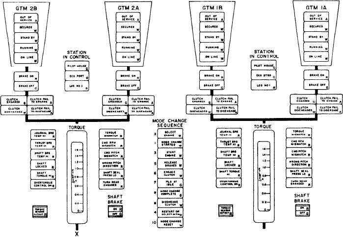
Figure 5-5.--Main center section of the DD MIMIC panel.
panels. The MIMIC panel provides a schematic
indicators were described under the GTM 2B
section of the engine No. 2 panel and will not be
representation of the four GTMs, clutches,
described again.
reduction gears, and shafts. For this reason it is
called the MIMIC panel. The left side of the
Main Center Section
MIMIC panel contains the status/alarm indicators
and manual start push-button control indicators
for the GTM 2A, an MRG bearing mimic on the
Figure 5-5 shows the main center section of
the DD and CG MIMIC panel. This section has
CG console, PLA and vibration meters, and
84 status/alarm indicators (80 on the CG console),
vibration select switches for GTM 2A and 2B. The
right side of the MIMIC panel is identical to the
2 meters, and 4 push-button control indicators.
We will only describe one engine of the left
left but labeled for GTM 1A and 1B. The main
engine group mimic section, as the indicators are
center part of the MIMIC panel displays the status
of each GTM, which station has control of the
identical for both engines and engine groups. The
only difference in the engine groups is the left one
individual engine rooms, which engines are
is labeled GTM 2B/GTM 2A, while the right one
connected to the main shaft, the alarms and status
is labeled GTM 1B/GTM 1A.
indicators for the individual engines, and the
Starting with the first status indicator under
automatic mode selectors (ENGINE SELECT,
the GTM 2B label is an indicator labeled OUT
PLANT MODE CONTROL, and PLANT MODE
OF SERVICE. It illuminates amber when the key
SELECT).
switch at the PLCC is in the out of service
GTM 2A Section
position. When illuminated, it prevents start of
the GTM. The status indicator labeled SECURED
The GTM 2A section is a mirror image of the
illuminates white if the auxiliary systems are not
GTM 2B section. The alarm indicators and status
5-12

