
On the CG MIMIC panel, the first two dual-
panel, is a mirror image of the GTM 2B
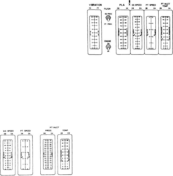
indicating meters are labeled VIBRATION
MANUAL START section. It has alarm indicators
GG/PT and PLA 2B/2A. Associated with these
and status indicators identical to the GTM 2B
two meters are two toggle switches labeled
section. These were described under the GTM 2B
FILTER GG FREQ/PT FREQ and ENGINE
MANUAL START section of the engine No. 2
2A/2B. These meters and toggle switches are
panel and will not be described again.
identical to the PLA and vibration meters
Lower Center Section
described previously for the DD console. The next
three dual-indicating meters are labeled GG
The lower center section of the DD MIMIC
SPEED 2B/2A, PT SPEED 2B/2A, and PT
panel has 8 dual-indicating meters (4 for each
INLET TEMP 2B/2A. These meters are identical
engine group) (10 on the CG PACC, with 5 for
to those described on the DD console. A
each engine group), 2 ENGINE SELECT sections
difference in the CG console is that it does NOT
that have 2 push-button control indicators, a
have a PT INLET pressure meter.
PLANT MODE CONTROL section with 4 push-
button control indicators, and a PLANT MODE
SELECT section that has 3 push-button control
indicators. The CG MIMIC panel also has 4 two-
position toggle switches. We will only describe the
meters for the engine 2B and 2A group. The
meters for the engine 1B and 1A group are
identical.
The first two dual-indicating meters on the DD
console, under the headings GG SPEED and PT
SPEED, are both labeled 2B and 2A. The signals
displayed on these meters originate at the GG and
PT speed pickups of the respective engines. The
GG speed pickup is located on the accessory
gearbox. The PT speed pickups (two) are located
in the turbine rear frames. The speed meters read
The last five dual-indicating meters on the CG
in rpm. The next two dual-indicating meters,
MIMIC panel are mirror images of the five just
under the heading PT INLET, are labeled PRESS
described. Remember, the only difference in the
2B/2A and TEMP 2B/2A. These meters display
2
meters is their label for the engine 1B and 1A
the pressure (in psia) and temperature (F x 10 )
group.
of the respective engines. The signals displayed
The ENGINE SELECT sections at the lower
on these meters come from sensors in the respective
center of the MIMIC panel are located on the
engine's turbine midframe. The pressure sensors
lower left and right sides of the panel. Each
are probes that pressurize a transducer, and the
section has two push-button control indicators
temperature sensors are thermocouples.
labeled 2B and 2A and 1B and 1A, respectively.
The last four dual-indicating meters' are
These push-button indicators illuminate green to
mirror images of the four just described.
indicate the engine(s) selected by the PACC
Remember, the only difference in the meters is
operator for a start/stop sequence.
their label for the engine 1B and 1A group.
The section labeled PLANT MODE CON-
TROL has four push buttons. They are labeled
CHANGE ENGINE, ENGINE RESTART,
START MODE CHANGE, and RESET. The
change engine command allows for GTMs in the
same engine room to be rotated on and off line
automatically when in the split-plant mode. The
change engine mode begins when the START
MODE CHANGE and CHANGE ENGINE push
buttons are depressed simultaneously. This
initiates a sequence that will start the selected
engine, bring it up to speed, bring the other engine
to idle, and secure it (if requested). The system
5-16