
illuminate white at various stages in the start of
engine goes in and out of torque limiting, or
a GTM. Their sequence of illumination varies
remains illuminated as long as the engine is in
depending on which plant mode logic start of a
torque limiting.
GTM is selected. We will not describe the various
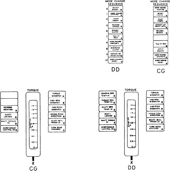
On the right side of the TORQUE meter are
mode changes in this TRAMAN. For detailed
five alarm indicators. The first one, labeled
information on the plant mode change sequence,
TORQUE MISMATCH, illuminates red when a
consult the applicable NAVSEA technical manual
discrepancy exists between actual shaft torque and
for either the DD- or CG-class ships. The
computed shaft torque. The next one, labeled
indicators on the DD console are labeled as
CMD RPM MISMATCH, illuminates red if a
follows from top to bottom: SELECT ENGINE,
discrepancy exists between actual shaft rpm and
MODE CHANGE STARTED, START ENGINE,
commanded shaft rpm. The third indicator,
RELEASE BRAKES, ENGAGE CLUTCH, PLA
labeled CMD PITCH MISMATCH, illuminates
AT IDLE, MODE CHANGE COMPLETE, DIS-
red if a discrepancy exists between actual pitch
ENGAGE CLUTCH, RESTART OR SELECT
and commanded pitch. The alarm indicator
ALTN, and MODE CHANGE RESET. The
labeled WRONG PITCH DIRECTION illuminates
indicators on the CG console are labeled as
red if the actual pitch moves in the opposite
follows from top to bottom: MODE CHANGE
direction from the commanded pitch setting. The
STARTED, SELECT ENGINE, START ENGINE,
last one, labeled SHAFT SEAL PRESS LO,
RESTART OR SELECT ACTN, RELEASE
illuminates red when the cooling/sealing water
BRAKES, PLA AT IDLE, APPLY BRAKES,
pressure to the propeller shaft seal drops below
MODE CHANGE COMPLETE, and MODE
12 psig. The status indicator labeled TURN
CHANGE RESET.
GEAR ENGAGED illuminates red when the
MRG turning gear is engaged.
Three alarm indicators, located to the left of
the edgewise meter labeled TORQUE on the CG
MIMIC panel, are different. We will describe these
indicators that are located at the same position
as those described on the DD MIMIC panel.
The first two alarm indicators on the left side
are blank. The alarm indicator labeled REVERSE
ROTATION monitors the shaft rotation and
illuminates red if the shaft is rotating in the reverse
direction from designed rotation. The rest of the
alarm indicators on this section are identical to
the DD console alarm indicators.
Between the engine group sections under the
label MODE CHANGE SEQUENCE are the 10
status indicators (9 on the CG console) that
5-14