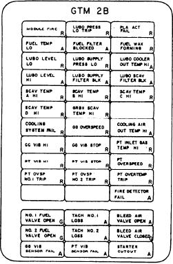
open. The alarm indicator labeled GG OVER-
a speed sensor failure). The last status indicator
SPEED illuminates red if the GG speed is > 9700
on the twelveth row is labeled BLEED AIR
rpm. The alarm indicator labeled COOLING AIR
VALVE OPEN. It illuminates amber when the
OUT TEMP HI illuminates amber when the
bleed air valve is open. The last status indicator
module cooling air is > 350F.
on the thirteenth row is labeled BLEED AIR
VALVE CLOSED. It illuminates green when the
On the eighth row, the first alarm indicator
bleed air valve is closed.
is labeled GG VIB HI. It illuminates red when the
GG vibration is at 6 mils or higher. The alarm
The first two alarm indicators on the four-
indicator labeled GG VIB STOP illuminates red
teenth row are labeled GG VIB SENSOR FAIL
when an auto shutdown of the GTM at a GG
and PT VIB SENSOR FAIL. They are a pair of
vibration of 7 mils occurs. The alarm indicator
functionally identical indicators. These two alarm
labeled PT INLET GAS TEMP HI illuminates
indicators are NOT on the CG console. They
red if T5.4 is > 1500F.
illuminate amber if one of the GG or one of the
PT vibration sensors fail. The last status/alarm
On the ninth row, the first alarm indicator is
indicator labeled STARTER CUTOUT illuminates
labeled PT VIB HI. It illuminates red when power
amber if the starter fails during a start or when
turbine vibration is at 7 mils or higher. The alarm
the GG speed reaches 4500 rpm and the start air
indicator labeled PT VIB STOP illuminates red
valve closes.
when an auto shutdown of the GTM occurs at
a power turbine vibration of 10 mils. The alarm
indicator labeled PT OVERSPEED illuminates
red if power turbine speed exceeds 3700 rpm.
On the tenth row, the next pair of alarm
indicators, labeled PT OVSP NO 1 TRIP and PT
OVSP NO 2 TRIP, are functionally identical
indicators. They illuminate red when an auto
shutdown of the GTM occurs. This is caused by
the respective PT speed sensor detecting a PT
speed of 3960 40 rpm. The alarm indicator
labeled PT OVERTEMP TRIP illuminates red if
an auto shutdown of the GTM occurs due to T5.4
exceeding 1625F.
On the CG console, the first alarm indicator
on the eleventh row is labeled MDL ACCESS
DOOR OPEN. It illuminates amber when a door
on the GTM module is open. The alarm indicator
labeled FIRE DETECTOR FAIL illuminates
amber if the fire detection circuitry fails or
if a UV sensor in the GTM fire detection system
fails.
The first status indicators on the twelveth and
Under the label TORQUE is a dual-indicating
thirteenth rows are labeled NO 1 FUEL VALVE
meter labeled 2B and 2A. This meter indicates the
OPEN and NO 2 FUEL VALVE OPEN. They
torque output of the respective PTs and reads in
are a pair of functionally identical indicators.
ft/lb. The signals to these meters come from the
They illuminate green to indicate the respective
respective GTMs and are conditioned by the FSEE
fuel supply valve is open. The second status/alarm
before being sent to the console for display. Under
indicators on the twelveth and thirteenth rows are
the label GTM LUBE OIL PRESS is a dual-
labeled TACH NO. 1 LOSS and TACH NO. 2
indicating meter labeled 2B and 2A. This meter
indicates the GTM LO supply pressure of the
LOSS. They are a pair of functionally identical
indicators. They illuminate amber if the respective
respective GTM. The signals for these meters
speed sensor detects a PT speed of < 100 rpm (or
come from the discharge side of the respective LO
5-7

