5. Turn the FLOW SELECTOR valve to the
REGULATOR position and close the VENT
AMBIENT valve.
6. Slowly move the PRESSURE SELEC-
TOR valve to the H2O position.
7. Turn the LEAKAGE SELECTOR valve
to the LOW position.
8. Open the LEAKAGE CONTROL valve.
Apply and maintain 17.0 inches of H2O to
regulator outlet. Maximum allowable leakage is
0.12 lpm (120 ccm).
9. Close the LEAKAGE CONTROL valve.
10. Back out on the LOW PRESSURE
REGULATOR and bleed the pressure with the
SYSTEM BLEED valve.
11. Turn the LEAKAGE SELECTOR valve
to the HIGH RANGE position.
12. If excessive leakage is found, locate the
probable cause using the troubleshooting chart,
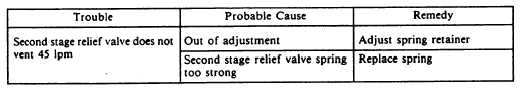
table 12-10. If the relief valve does not vent, locate
the probable cause by using the troubleshooting
chart, table 12-11.
FLOW SUCTION TEST.— This test deter-
mines how much suction will be required by the
user to achieve or receive a given amount of
oxygen or air/oxygen mixture through the
regulator. To perform the flow suction test,
proceed as follows:
1. Disconnect the hose from the LOW
PRESSURE connection and REFERENCE TAP
connection inside the altitude chamber.
2. Turn vacuum pump ON.
3. Ensure that the PRESSURE SELECTOR
Valve is in the H2O position.
4. Ensure that the regulator diluter control
lever is in the 100-percent OXYGEN position.
5. Ensure that the INLET PRESSURE
ON/OFF valve is ON.
6. Ensure that the regulator supply valve
control lever is in the ON position.
7. By using the LOW PRESSURE REGU-
LATOR, set the inlet pressure at each inlet pres-
sure specified on the Performance Test Sheet.
8. By using the OUTPUT valve, set flows
specified in the Performance Test Sheet on
the OUTPUT manometer. Readings must be
recorded with the regulator diluter control lever
in both NORMAL and 100-percent OXYGEN
positions for each outlet flow specified on the
Performance Test Sheet. Suction values will be
displayed on PRESSURE/SUCTION manome-
ter. With no suction on the regulator (OUTPUT
valve closed), maximum flow through regulator
should not exceed 0.01 lpm. This will cause a
slight rise in the PRESSURE/SUCTION ma-
nometer reading.
Record readings on the
Performance Test Sheet.
9. Close OUTPUT valve.
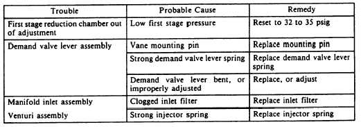
10. If the regulator fails the flow suction test,
locate the probable cause by using the
troubleshooting chart in table 12-12.
Table 12-11.—Troubleshootig (Second Stage Relief Valve Test)
Table 12-12.—Troubleshooting (Flow Suction Test)
12-15