2. Place the emergency pressure control lever
in the EMERGENCY position.
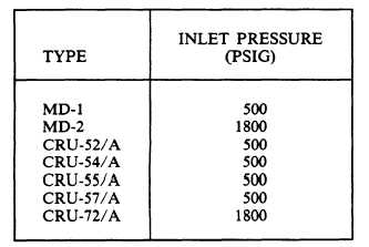
3. Using HIGH PRESSURE REGULATOR,
apply pressure specified in table 12-6 to the
regulator inlet.
Slowly turn the INLET
PRESSURE ON/OFF valve to ON.
4. Draw a film of leak detection compound
(MIL-L-25567) across the regulator outlet fitting.
As in the last test, see if there is any distention
of the film.
5. There is no allowable leakage. If leakage
is noted, locate probable cause using
troubleshooting chart, table 12-7.
6. Place the emergency control lever in the
NORMAL position.
OVERALL LEAKAGE TEST.— Test, by
trapping pressure in the regulator, for any leakage
anywhere on or in the regulator. Perform the
overall leakage test first with diluter lever in its
100-percent OXYGEN position, and then repeat
it with the lever in the NORMAL OXYGEN
position.
1. Place regulator oxygen supply valve lever
in the ON position, and emergency pressure
control lever in the NORMAL position.
2. By using test stand HIGH PRESSURE
REGULATOR, apply pressure specified in table
12-8 to regulator inlet.
3. Turn INLET PRESSURE ON/OFF valve
to OFF. Leave the regulator oxygen supply valve
lever in the ON position.
4. Leakage will be indicated on the regulator
pressure gauge. Allowable leakage should not
exceed 60 psig over a 2-minute period. Repeat the
test with the diluter lever turned to NORMAL
OXYGEN.
Table 12-6.—Inlet Pressure (Oxygen Supply Valve Leakage
Test)
12-12
5. If allowable leakage is exceeded, locate the
probable cause by using the troubleshooting chart,
table 12-9.
6. Turn the HIGH PRESSURE REGULA-
TOR to VENT.
7. Bleed the regulator by placing the emer-
gency pressure control lever in the EMERGENCY
position. Return the lever to NORMAL.
8. Bleed the test stand using the SYSTEM
BLEED valve.
REGUI.ATOR PRESSURE GAUGE SCALE
AND ERROR TEST.— This test ensures that the
pressure gauge is operating properly and within
tolerance. To perform the regulator pressure
gauge scale and error test, proceed as follows:
1. Turn the INLET PRESSURE ON/OFF
valve to ON. The LOW PRESSURE REGULA-
TOR can only be used when applying pressures
below the gauge guard setting (165 to 175 psig)
to an item under test. For pressures above the
gauge guard setting, the HIGH PRESSURE
REGULATOR must be used.
2. Using LOW PRESSURE REGULATOR
(N), slowly increase the pressure to each test
pressure in 100 psig increments and below, as
specified in table 12-6. Record the regulator
pressure gauge readings twice, once before and
once after tapping regulator pressure gauge.
3. Check the tolerance by comparing the
regulator pressure gauge reading with the test
stand INPUT PRESSURE gauge.
4. Back out on the LOW PRESSURE
REGULATOR.
5. Continue the test for 500 psig pressure by
using the HIGH PRESSURE REGULATOR.
6. Turn the HIGH PRESSURE REGULA-
TOR to VENT.
7. Bleed the test standby using the SYSTEM
BLEED valve. Bleed the regulator using the
emergency pressure control lever.
OUTWARD LEAKAGE TEST.— In per-
forming this test, the relief valve is not covered.
The allowable leakage through this valve at 17.0
inches H2O is included in the maximum allowable
leakage of 120 ccm.
NOTE: This text uses the abbreviations
lpm for liters per minute. Newer equipment
and technical manuals may use the correct
abbreviation, which is L/min.