5. Adjust the LOW PRESSURE REGULA-
TOR until 70 psig is indicated on the
REGULATED LOW PRESSURE gauge.
6. Turn the PRESSURE SELECTOR valve
to the H2O position, and slowly open the
LEAKAGE CONTROL valve until 17.0 inches
of H2O is indicated on PRESSURE/SUCTION
manometer. By adjusting the LEAKAGE CON-
TROL, you maintain 17.0 inches of H2O indica-
tion throughout this test.
7. If no leakage is indicated on the HIGH
RANGE LEAKAGE rotameter, turn the LEAK-
AGE SELECTOR valve to the low range posi-
tion, and check for an indication of leakage on
the low RANGE LEAKAGE rotameter.
Allowable leakage is 0.12 lpm (120 ccm).
8. Switch the LEAKAGE SELECTOR valve
to HIGH position, and close the LEAKAGE
CONTROL valve.
9. Repeat steps 6, 7, and 8 with the diluter
control lever in the 100-percent OXYGEN
position.
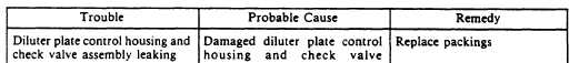
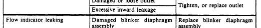
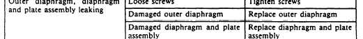
10. If leakage is excessive, locate its probable
cause using troubleshooting chart, table 12-10.
SECOND STAGE RELIEF VALVE TEST.—
To perform the second stage relief valve test,
proceed as follows:
1. Turn the PRESSURE SELECTOR valve
to the Hg position, and place the FLOW
SELECTOR valve in the CONTROLLER
position.
2. Ensure the diluter control lever is in the
100-percent OXYGEN position.
3. Using the VENT PRESSURE valve, slowly
apply 3 inches of mercury to the regulator outlet.
The regulator relief valve should be venting at
least 45 lpm, as indicated on the vent flow
manometer.
4. Close the VENT PRESSURE valve and
bleed the pressure down to 0 in Hq using VENT
AMBIENT valve. Close the valve.
Table 12-10.—Troubleshooting (Outward Leakage Test)
12-14