The cylinder and ram assembly constitutes the
actual engine of the arresting gear. It is located within
the engine structure between the movable crosshead
and the cylinder outlet elbow on the engines.
The
cylinder
is
a
machined,
forged
steel,
smooth-bore tube, open on both ends and large enough
to provide a working area for the ram and to house the
fluid necessary for aircraft arrestments. It is supported
within the engine structure by cylinder support saddles.
One end of the cylinder is clamped and bolted with four
cylinder clamps and Allen bolts to the cylinder outlet
elbow. The other end receives the ram
The ram is a large, hollow steel piston that is moved
in and out of the cylinder by the crosshead. It is bored to
reduce the weight, although it is not bored completely
through. The inner end (the end that fits in the mouth of
the cylinder) is solid and provides a working area
between the ram and engine fluid during arrestments.
The inner end of the ram contains a set of V-ring
packing to provide a seal for the engine fluid between
the cylinder wall and the ram also the inner end of the
ram is stepped to accommodate a cage and slippers,
which provide a bearing surface for the ram as it slides
in and out of the cylinder.
The outer (open) end of the hollow steel ram is
clamped into a socket on the crosshead by a split flange,
which fits into an annular groove near the end of the
ram.
CROSSHEAD AND FIXED SHEAVE
INSTALLATION
The principle involved in the operation of the
crosshead and fixed sheaves is that of a block and
tackle. The purchase cables are reeved around the
sheaves of the crosshead and fixed sheave assemblies.
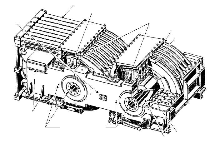
The crosshead is a three-piece welded structure with
two hollow steel shafts clamped between its outer
sections and the center section. The crosshead body is
clamped to the outer end of the ram by a split flange,
which fits into an annular groove around the end of the
ram. Figure 3-16 illustrates the crosshead.
The crosshead contains two similar banks of
sheaves, with nine sheaves in each bank. The sheaves
located outboard on the crosshead are 33-inch pitch
diameter, and the sheaves located on the inboard shaft
are 28-inch pitch diameter. The difference in the pitch
diameter of the two banks of sheaves is necessary so
that the purchase cable reeved around the outboard
3-18
CAUTION
PLATE
FAIRLEAD TUBES
SHEAVE (28” P.D.)
DEPTH GAUGE BRACKETS
FAIRLEAD
SHEAVE (33” P.D.)
ROLLER BEARING
SHAFT
SLIPPERS
LUBRICATION PORTS FOR
LUBRICATION SYSTEM
ABEf0316
Figure 3-16.—Crosshead assembly.


