MAIN CONTROL PANEL
The control panel is the control center for the
arresting engine. (See fig. 3-14.) It provides a means for
the operator to centrally regulate the air pressure in the
system, keep a check on the fluid temperature, and
energize the electrical system. The control panel is also
equipped with a cable anchor damper light box.
The control panel is a rectangular sheet of steel
mounted on the engine structure on the CRO-valve side
of the engine.
Three air manifolds are located on the control
panel: a main air-charging manifold with high-pressure
air piping leading from the ship's high-pressure air
supply system; an air manifold for the auxiliary air
flasks; and a manifold for the accumulator. The main
air-charging manifold is equipped with an air-charging
valve, which is closed except when taking on air from
the ship's high-pressure air supply system to charge the
auxiliary air flasks and accumulator.
High-pressure air piping is provided from the main
air-charging manifold to the auxiliary air flask
manifold and the accumulator manifold. The auxiliary
air flask and accumulator manifolds each have
air-charging valves, gauge valves, and a pressure
gauge. The auxiliary air flask charging valve allows for
charging the auxiliary air flasks or emergency charging
of the accumulator from the air flasks. The auxiliary air
flask pressure gauge monitors the air pressure of the
auxiliary air flasks. The accumulator charging valve
allows for charging of the accumulator and air
expansion flask. The accumulator pressure gauge
monitors the air pressure of the accumulator and air
expansion flask.
A fuse switch box is mounted at the end of the
control panel and contains the main switches for
activating the electrical system of the arresting gear.
The cable anchor damper battery position indicator
light box on the control panel contains a power ON and
OFF switch and three indicator lights. A white light
indicates the power switch is on. Two green lights give
battery position indication of the cable anchor dampers.
CYLINDER AND RAM ASSEMBLIES
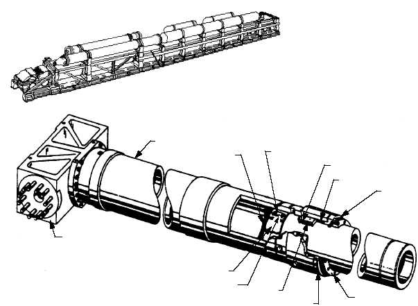
The cylinder acts as a receiver for the ram and as a
reservoir for the fluid to be displaced by the ram. Figure
3-15 illustrates the cylinder and ram assembly of the
Mod 3 arresting engine.
3-17
ELBOW
ASSEMBLY
CYLINDER
CAGE RETAINER
RAM
RAM SLIPPER
CAGE
RETAINER
WIPER
RETAINER
RAM CAGE
SLIPPER
V-RING
PACKING
SPLIT
WIPER
ABEf0315
Figure 3-15.—Cylinder and ram assembly.

