bolted to the air expansion flask manifold. The fluid
end of the accumulator is flanged and bolted to the
accumulator nozzle, which contains a fluid-level
indicator, a device used to indicate to the engine-room
operator whether the system has the proper amount of
fluid. The fluid indicator registers the following three
conditions—DRAIN (excessive amount of fluid in the
system), BATTERY (proper amount of fluid in the
system), and FILL (insufficient amount of fluid in the
system).
The floating air-fluid separator piston is made of
aluminum alloy and has two sets of V-ring packing (one
for the air side and one for the fluid side), which prevent
air from leaking past the piston into the fluid side of the
accumulator, or fluid from leaking into the air side. Two
slipper cages with phenolic slippers are fitted onto the
piston to act as a bearing surface between the piston and
the cylinder wall. The phenolic slippers are replaceable
and must be replaced when the maximum allowable
wear has been reached. This is to prevent
metal-to-metal wear between the piston and the
accumulator wall. An eyebolt is provided on the air side
of the piston to aid in removing the piston from the
accumulator when maintenance is required. The fluid
side of the piston has a striker rod that actuates a
fluid-level indicator located in the accumulator nozzle.
The fluid-level indicator has a drive shaft that
extends through the nozzle from side to side and is
secured in place by flanges and bolts. O-rings provide a
seal against leakage of fluid around the drive shaft.
Gears are secured onto the shaft inside the nozzle.
These gears mate with teeth on the actuator rod, which
extends fore and aft in the nozzle, and the
fluid-indicator rod, which is vertical and extends
through the top of the nozzle. An O-ring prevents
leakage around the indicator rod. When the striker rod
on the piston makes contact with the actuator rod, the
drive shaft rotates, causing the indicator rod to move
down. See figure 3-9.
An indicator plate is mounted on top of the nozzle.
The plate has the readings DRAIN, BATTERY, and
FILL. The indicator rod is a differential rod; and any
time the piston striker rod is not in contact with the
actuator rod, accumulator pressure working on the
differential area of the indicator rod will cause the
indicator rod to rise to the DRAIN position. The engine
crosshead must always be in its BATTERY position
when the fluid level of the arresting engine is checked.
FLUID REPLENISHMENT
SYSTEM
LEARNING OBJECTIVE: Describe the
components of the fluid replenishment system.
In any hydraulic system, small amounts of fluid are
lost due to leakage. Fluid also contracts when cold and
expands when hot. To compensate for leakage and
expansion or contraction of the hydraulic fluid in the
hydraulic system of the Mk 7 arresting engines, a fluid
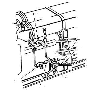
replenishment system is provided. See figure 3-10.
The fluid replenishment system consists of a small
hand pump, mounted on the lower engine frame that is
connected by piping to the engine accumulator and a
6-gallon stowage tank. If, because of leakage or fluid
contraction while the engine crosshead is in BATTERY,
the fluid-level indicator reads FILL, the supply valve in
the piping is opened and the hand pump is operated
until the indicator reads BATTERY. A fluid filter is
located in the supply line to filter the fluid being
pumped into the accumulator. If the fluid-level
indicator reads DRAIN, the return valve located in the
return line is opened, and fluid from the accumulator
drains into the replenishment tank. When the fluid-level
indicator reads BATTERY, the return valve is closed.
3-13
VALVE
(RETURN)
STRAINER
FILTER
TANK
HAND
PUMP
FLUID
LEVEL
INDICATOR
VALVE
(SUPPLY)
ABEf0310
Figure 3-10.—Fluid replenishment system.