because of the staggered arrangement of the vertical
engaging straps.
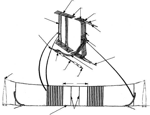
The second barricade configuration (fig. 3-38) is
the E-2/C-2 barricade. A 40 foot opening in the center
of the webbing is designed so that props of the E-2/C-2
aircraft can pass through it with minimal damage to
aircraft during arrestment. The E-2/C-2 barricade
installation is comprised of an uncoated, double
webbing assembly which is factory preassembled,
boxed and shipped ready to rig.
DECK RAMPS
There are 12 portable deck ramps. They should be
numbered 1 through 12 from port to starboard. The
numbering should be large enough to facilitate easy
identification
and
placement
in
corresponding
positions on the flight deck.
The purpose of the deck ramps is to secure the
lower load straps in place and cause the aircraft nose
wheel to ride up and into the barricade assembly. This
protects the lower load straps and also prevents the
aircraft from nosing under them during a barricade
arrestment.
Deck ramps are normally installed by V-1 division
personnel during barricade rig evolutions.
MULTIPLE-RELEASE ASSEMBLY
The
multiple-release
assemblies
provide
the
connection between the upper and lower load straps of
the barricade and the tensioning pendants of the
barricade stanchions. They serve to release the webbing
assembly during an aircraft engagement (figs. 3-36 and
3-38.)
The multiple-release assembly consists of a
number of release straps attached to loops at the ends of
3-37
PELICAN HOOK ASSEMBLY
AND UPPER TENSION
PENDANT
TWO
WEBBING
ASSEMBLIES
40'
LOADING STRAPS
STRAP CLIPS
RELEASE STRAPS
ENGAGING STRAPS
PARALLEL PENDANT
U-SHACKLE
EXTENSION LOOPS
EXTENSION
PENDANT
PURCHASE CABLE
RED MARKER STRAPS
DECK RAMPS
CONNECTIONS STRAPS
LOWER TENSIONING
PENDANT
BOOT
STANCHION
ABEf0338
Figure 3-38.—E2/C2 aircraft barricade installation.